To anyone trying something similar in the future
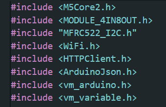
MODULE_4IN8OUT module;
MFRC522_I2C mfrc522(0x28, -1, &Wire);
void setup() {
M5.begin(true, true, true, true);
Serial.begin(115200);
delay(500);
Serial.println("Starting setup...");
M5.Lcd.println("Init...");
// POWER MANAGEMENT dla Port A (RFID)
M5.Axp.SetBusPowerMode(0);
M5.Axp.SetLDOEnable(2, true);
delay(200);
// --- I2C BUSES ---
Wire.begin(32, 33, 100000);
Wire1.begin(21, 22, 100000);
delay(100);
M5.Lcd.println("Init 4IN8OUT...");
// Start module 4IN8OUT
if (!module.begin(&Wire1, 21, 22, MODULE_4IN8OUT_ADDR)) {
M5.Lcd.setTextColor(RED);
M5.Lcd.println("4IN8OUT INIT FAIL");
Serial.println("4IN8OUT INIT FAIL");
while (1) delay(1000);
}
M5.Lcd.setTextColor(GREEN);
M5.Lcd.println("4IN8OUT OK!");
Serial.println("4IN8OUT OK!");
M5.Lcd.setTextColor(WHITE);
// Init RFID
mfrc522.PCD_Init();
M5.Lcd.println("RFID OK!");
Serial.println("RFID OK!");