@wsanders This problem was caused by a reference to an uninitialized variable in that drawSomeTextOnScreen() function. As usual, the invalid reference caused weird behavior that was unrelated to the actual problem.
W
Offline
Posts
-
RE: [SOLVED} PaperS3 Touch Screen Latency
-
[SOLVED} PaperS3 Touch Screen Latency
I'm trying to make some progress on making the PaperS3 touch screen useful. I have the following code:
void loop(void)
{
    // necessary:
    M5.update();
    t = M5.Touch.getDetail(0);
    if (t.state > 0) {
      Serial.printf("Index:%d Count:%d IsPressed:%d Touch:%s\n",eventindex,eventcount,t.isPressed(), state_name[t.state]);
    }
    if (t.state == 14 || t.state == 10) {
      // on flick end or drag end
      drawSomeTextOnScreen();
    }
    delay(2);
}
The code properly detects the flick end or drag end event, but then there is about a 10 second delay before anything happens and the text is drawn on the screen.
Am I doing this right?
What is the device doing in the 10 seconds between the flick end or drag end and the time the screen starts to update?(FWIW delays in the loop of up to 50 msec seem reasonable. M5.Power.lightSleep disables interrupts and the device losts its mind (including serial output.) Does using the arduino delay call save any power anyway? )
The sample drawing program works fine, but it is just testing for t.isPressed():
void loop() { M5.update(); delay(20); t = M5.Touch.getDetail(); if (t.isPressed()) { M5.Display.fillCircle(t.x, t.y, 15, BLACK); } } -
RE: Anybody get drawJpgFile to work with M5 PaperS3?
@wsanders Bump. For future reference, the easiest way to get a static image into Arduino IDE code is to convert the image into an XBM with Gimp and use M5.Display.drawXBitmap. More here: https://github.com/wsanders/M5PaperS3-Stuff
-
RE: Board Manager 2.1.4 Failure in Arduino 1.8.19 IDE
@kuriko I believe so, but now that I've patched M5Unified, I'd need to unpatch and test again. I'll report back if anything further happens.
-
Board Manager 2.1.4 Failure in Arduino 1.8.19 IDE
M5Unfied version 0.2.7 installed. Do I need to use IDE 2 now? Trying to compile for PaperS3.
Workedaround by commenting out all references to M5StamPLC and M5Tab5 (some are bypassed by #ifdefs and don't have to be deleted):
Arduino: 1.8.19 (Linux), Board: "M5PaperS3, Disabled, OPI PSRAM, QIO 80MHz, 16MB (128Mb), Core 1, Core 1, Hardware CDC and JTAG, Enabled, Disabled, Disabled, UART0 / Hardware CDC, 16M Flash (3MB APP/9.9MB FATFS), 240MHz (WiFi), 921600, None, Disabled" /home/wsanders/Documents/ArduinoSketchbook/libraries/M5Unified/src/M5Unified.cpp:83:12: error: 'board_M5StampPLC' is not a member of 'm5::board_t' {aka 'lgfx::boards::board_t'} { board_t::board_M5StampPLC , GPIO_NUM_15,GPIO_NUM_13 , GPIO_NUM_1 ,GPIO_NUM_2 }, ^~~~~~~~~~~~~~~~ /home/wsanders/Documents/ArduinoSketchbook/libraries/M5Unified/src/M5Unified.cpp:148:12: error: 'board_M5StampPLC' is not a member of 'm5::board_t' {aka 'lgfx::boards::board_t'} { board_t::board_M5StampPLC , GPIO_NUM_7, GPIO_NUM_8, GPIO_NUM_9, GPIO_NUM_10 }, ^~~~~~~~~~~~~~~~ /home/wsanders/Documents/ArduinoSketchbook/libraries/M5Unified/src/M5Unified.cpp:167:12: error: 'board_M5StampPLC' is not a member of 'm5::board_t' {aka 'lgfx::boards::board_t'} { board_t::board_M5StampPLC , GPIO_NUM_21 }, ^~~~~~~~~~~~~~~~ /home/wsanders/Documents/ArduinoSketchbook/libraries/M5Unified/src/M5Unified.cpp: In member function 'void m5::M5Unified::_begin(const m5::M5Unified::config_t&)': /home/wsanders/Documents/ArduinoSketchbook/libraries/M5Unified/src/M5Unified.cpp:1237:19: error: 'board_M5StampPLC' is not a member of 'm5::board_t' {aka 'lgfx::boards::board_t'} case board_t::board_M5StampPLC: ^~~~~~~~~~~~~~~~ /home/wsanders/Documents/ArduinoSketchbook/libraries/M5Unified/src/M5Unified.cpp: In member function 'void m5::M5Unified::_begin_spk(m5::M5Unified::config_t&)': /home/wsanders/Documents/ArduinoSketchbook/libraries/M5Unified/src/M5Unified.cpp:1554:21: error: 'board_M5StampPLC' is not a member of 'm5::board_t' {aka 'lgfx::boards::board_t'} case board_t::board_M5StampPLC: ^~~~~~~~~~~~~~~~ /home/wsanders/Documents/ArduinoSketchbook/libraries/M5Unified/src/M5Unified.cpp: In member function 'virtual void m5::M5Unified::update()': /home/wsanders/Documents/ArduinoSketchbook/libraries/M5Unified/src/M5Unified.cpp:1821:21: error: 'board_M5Tab5' is not a member of 'm5::board_t' {aka 'lgfx::boards::board_t'} case board_t::board_M5Tab5: ^~~~~~~~~~~~ /home/wsanders/Documents/ArduinoSketchbook/libraries/M5Unified/src/M5Unified.cpp:1953:19: error: 'board_M5StampPLC' is not a member of 'm5::board_t' {aka 'lgfx::boards::board_t'} case board_t::board_M5StampPLC: ^~~~~~~~~~~~~~~~ /home/wsanders/Documents/ArduinoSketchbook/libraries/M5Unified/src/M5Unified.cpp: In member function 'void m5::M5Unified::setTouchButtonHeightByRatio(uint8_t)': /home/wsanders/Documents/ArduinoSketchbook/libraries/M5Unified/src/M5Unified.cpp:2044:19: error: 'board_M5Tab5' is not a member of 'm5::board_t' {aka 'lgfx::boards::board_t'} case board_t::board_M5Tab5: ^~~~~~~~~~~~ exit status 1 Error compiling for board M5PaperS3. This report would have more information with "Show verbose output during compilation" option enabled in File -> Preferences. -
RE: M5Unified 0.2.3 broken on PaperS3
Still a problem:
Arduino: 1.8.19 (Linux), Board: "M5PaperS3, Disabled, OPI PSRAM, QIO 80MHz, 16MB (128Mb), Core 1, Core 1, Hardware CDC and JTAG, Enabled, Disabled, Disabled, UART0 / Hardware CDC, 16M Flash (3MB APP/9.9MB FATFS), 240MHz (WiFi), 921600, None, Disabled"

/home/wsanders/Documents/ArduinoSketchbook/libraries/M5Unified/src/M5Unified.cpp: In static member function 'static bool m5::M5Unified::_speaker_enabled_cb_atomic_echo(void*, bool)':
/home/wsanders/Documents/ArduinoSketchbook/libraries/M5Unified/src/M5Unified.cpp:338:10: error: variable 'spk_cfg' set but not used [-Werror=unused-but-set-variable]
     auto spk_cfg = self->Speaker.config();
          ^~~~~~~
/home/wsanders/Documents/ArduinoSketchbook/libraries/M5Unified/src/M5Unified.cpp: In static member function 'static bool m5::M5Unified::_microphone_enabled_cb_atomic_echo(void*, bool)':
/home/wsanders/Documents/ArduinoSketchbook/libraries/M5Unified/src/M5Unified.cpp:441:10: error: variable 'spk_cfg' set but not used [-Werror=unused-but-set-variable]
     auto spk_cfg = self->Speaker.config();
          ^~~~~~~
cc1plus: some warnings being treated as errors
Multiple libraries were found for "WiFi.h"
 Used: /home/wsanders/.arduino15/packages/m5stack/hardware/esp32/2.1.3/libraries/WiFi
 Not used: /home/wsanders/arduino-1.8.19-NOSAVE/libraries/WiFi
exit status 1
Error compiling for board M5PaperS3.
M5GFX is now 0.2.5, M5United is 0.2.3, this bug comes from M5United, upgraded M5GFX is OK.
Too busy today to file a bug report on this, later.
-
M5Unified 0.2.3 broken on PaperS3
My sketches all fail to compile. I am using the 1.8.19 IDE on Linux, haven't moved to the 2.0 IDE yet :
Arduino: 1.8.19 (Linux), Board: "M5PaperS3, Disabled, OPI PSRAM, QIO 80MHz, 16MB (128Mb), Core 1, Core 1, Hardware CDC and JTAG, Enabled, Disabled, Disabled, UART0 / Hardware CDC, 16M Flash (3MB APP/9.9MB FATFS), 240MHz (WiFi), 921600, None, Disabled"

In file included from /home/wsanders/Documents/ArduinoSketchbook/libraries/M5Unified/src/M5Unified.h:5,
                 from /home/wsanders/Documents/ArduinoSketchbook/M5/badgeWX/badgeWX.ino:2:
/home/wsanders/Documents/ArduinoSketchbook/libraries/M5Unified/src/M5Unified.hpp: In member function 'virtual void m5::M5Unified::begin(m5::M5Unified::config_t)':
/home/wsanders/Documents/ArduinoSketchbook/libraries/M5Unified/src/M5Unified.hpp:326:62: error: no matching function for call to 'm5gfx::M5GFX::init_without_reset(bool&)'
       bool res = Display.init_without_reset(cfg.clear_display);
                                                              ^
In file included from /home/wsanders/Documents/ArduinoSketchbook/libraries/M5GFX/src/M5GFX.h:22,
                 from /home/wsanders/Documents/ArduinoSketchbook/libraries/M5Unified/src/M5Unified.hpp:19,
                 from /home/wsanders/Documents/ArduinoSketchbook/libraries/M5Unified/src/M5Unified.h:5,
                 from /home/wsanders/Documents/ArduinoSketchbook/M5/badgeWX/badgeWX.ino:2:
/home/wsanders/Documents/ArduinoSketchbook/libraries/M5GFX/src/lgfx/v1/LGFXBase.hpp:1411:10: note: candidate: 'bool lgfx::v1::LGFX_Device::init_without_reset()'
     bool init_without_reset(void) { return init_impl(false, false); };
          ^~~~~~~~~~~~~~~~~~
/home/wsanders/Documents/ArduinoSketchbook/libraries/M5GFX/src/lgfx/v1/LGFXBase.hpp:1411:10: note:   candidate expects 0 arguments, 1 provided
Multiple libraries were found for "WiFi.h"
 Used: /home/wsanders/.arduino15/packages/m5stack/hardware/esp32/2.1.3/libraries/WiFi
 Not used: /home/wsanders/arduino-1.8.19-NOSAVE/libraries/WiFi
exit status 1
With 0.2.2 I needed to use these includes, in this order:
#include <epdiy.h>
#include <M5Unified.h>
Maybe this has changed? Here's some sample code, it compiles with 0.2.2:
#include <epdiy.h> #include <M5Unified.h> static constexpr const char* state_name[16] = { "none" , "touch" , "touch_end" , "touch_begin" , "___" , "hold" , "hold_end" , "hold_begin" , "___" , "flick" , "flick_end" , "flick_begin" , "___" , "drag" , "drag_end" , "drag_begin" }; void setup(void) { Serial.begin(115200); M5.begin(); M5.Display.setRotation(M5.Display.getRotation() ^ 2); M5.Display.setEpdMode(epd_mode_t::epd_fastest); M5.Display.startWrite(); M5.Display.setTextSize(2); } void loop(void) { // too slow! M5.delay(10); M5.delay(2); M5.update(); // Count is going to be the bumber of "fingers" detected: 0, 1, max 2 // So, can be ignored for simple button press // Always seems to be 0 inside for loop? // auto count = M5.Touch.getCount(); auto t = M5.Touch.getDetail(0); if (t.state > 0) { // State is state of the entire touch screen // All we care about is t.wasFlicked Serial.print(t.state); Serial.println(state_name[t.state]); } M5.Display.display(); } -
What's the point of loopTask and appMain in ESP Arduino IDE?
Specifically, I am using a PaperS3. As I understand it, the Arduino IDE just runs all setup() and void() on one core unless you tell it otherwise. Or maybe the ESP library makes the Arduino IDE behave differently? AFAICT loopTask() and appMain() are used by the RTOS scheduler, so maybe the RTOS scheduler is installed by the Arduino IDE?
This code fragment is present in some sketches, like github.com/m5stack/M5Unified/blob/master/examples/Basic/Touch/DragDrop/DragDrop.ino:
#if !defined ( ARDUINO ) && defined ( ESP_PLATFORM ) extern "C" { void loopTask(void*) { setup(); for (;;) { loop(); } vTaskDelete(NULL); } void app_main() { xTaskCreatePinnedToCore(loopTask, "loopTask", 8192, NULL, 1, NULL, 1); } } #endif -
cfg.clear_display=false has no effect on PaperS3?
I might post this as a bug: cfg.clear_display = false seems to have no effect on the PaperS3. It would be useful to have it work because the device could be woken up without having to rewrite the whole screen. Perhaps this is a hardware limitation?
include <epdiy.h>
#include <M5Unified.h>

void setup() {
  auto cfg = M5.config();
  // This seems to have no effect:
  cfg.clear_display = false;
  M5.begin(cfg);
}
May ways to workaround for the time being.
-
RE: Icon on M5 paper
I would suggest formatting the icon as a XBM and the using drawXBitmap, no need to decode the bits yourself:
FOexample
#include "somexbm.h"
...
M5.Display.drawXBitmap(0, 0, xbm_bits, xbm_width, xbm_height, TFT_BLACK);
The .h file will have
#define xbm_width 540
#define xbm_height 960
static unsigned char xbm_bits[] = {
   0x00, 0x00, 0x00, 0x00, 0x00, 0x00, 0x00, 0x00, 0x00, 0x00, 0x00, 0x00, etc
You can easily produce an XBM file with GIMP or some other program. I don't remember the format, but I thiink the file is just a bitwise stream of pixels values.
-
Has anyone gotten M5.Rtc.setAlarmIRQ to work on ESP32S3? for
Trying to get M5.Rtc.setAlarmIRQ to work. Note: Device is PaperS3, so this function may not be implemented yet.
M5.Rtc.setAlarmIRQ(30);
M5.Power.powerOff();
This should reboot the device every 30 sec but doesn't.
M5.Power.timeSleep works, and is coded thus in Power_Class.cpp:
void Power_Class::timerSleep( int seconds )
{
  M5.Rtc.disableIRQ();
  M5.Rtc.setAlarmIRQ(seconds);
#if !defined (M5UNIFIED_PC_BUILD)
  esp_sleep_enable_timer_wakeup(seconds * 1000000ULL);
#endif
  _timerSleep();
}
However, for the PaperS3, M5UNIFIED_PC_BUILD is not defined, so the RTC timer call is not used, and the esp timer is called instead. I'm not sure why, because the PaperS3 has the same RTC chip as all the other M5 devices, and getting and setting the RTC clock seems to work. Yet, when I call M5.Rtc.disableIRQ and M5.Rtc.setAlarmIRQ separately in my code, it doesn't work.
It's also unclear form the ESP documentation is esp_sleep_enable_timer_wakeup even puts the ESP to sleep. You can put the ESP in deep sleep with a wakeup time, but the PaperS3 still drains about 5mA of power, much more than it should if it were completely powered off. (It is a known issue that M5.Power.powerOff doesn't completely power off the PaperS3, but this should not affect the Rtc alarm.)
I hope this is not a bug in the odd PMS150G power chip since that chip cannot be reprogrammed in the PowerS3.
Any ideas?
-
RE: Paper S3 questions
@felmue Your measurement for ESP deep sleep + Imu.sleep is accurate. My device is drawing the battery down about 5-7% per day, which is roughly 5ma.
I tested your patch. Unfortunately it doesn't seem to work once the RTC countdown timer is set. If one uses Power.shutdown, the Rtc timer is bypassed in the code in favor of the ESP timer since M5UNIFIED_PC_BUILD is not defined (why?).
Rtc.setAlarmIRQ does work in its integer form, if followed by Power.powerOff. I could not get Rtc.setAlarmIRQ to work in its date,time form.
Your patch does turn off the PaperS3 otherwise, but with the ESP completely powered down its timers aren't functional.
So I think we're stuck with ESP deep sleep for now. It would be interesting to see the code for the PMS150G. I'm not sure what all that FET logic around it is for, maybe an AXP192 wouldn't fit on the board. (And why a USB chip that would prevent the device from frying when plugged into a USB PM port wasn't included.)
I tested skipping M5.begin but the PaperS3 would do nothing. Tested with Display.init and it worked, but battery readings were undfined. Tested that with M5.Power.begin and battery readings were still undefined, probably because board_t isn't set.
Something besides the IMU is sucking that power though, the BMI270 should use less than 1ma even when fully awake. The PMS150G uses only a few uA when running, I don't think it ever turns off.
-
RE: Paper S3 questions
@felmue Are you sleeping the IMU with M5.Imu.sleep when you deep sleep the ESP? I think by default the IMU stays awake.
-
RE: Paper S3 questions
@felmue Thanks again ....
Sure enough, the device rebooted 4.25 hours after the last reboot this morning. This isn't too bad a limitation for my badge test skeptch, the sketch will set the date anyway, and if it's less than 4.25 hr before midnight it will still reset at midnight.
Digging deeper into setAlarmIRQ, the 255 min limit is not in the rtc_time_t instance; the rtc_time_t instance should be able to handle an alarm up to a week away.
So far, the LED has not illuminated after M5.Power.timerSleep does whatever it does.
You have to be care to actually send M5.Power.deepSleep the right uint64_t, something like:
M5.Power.deepSleep(1000000L * uint64_t(w), false);ESP deep sleep should be almost as good as a power off, assuming setAlarmIRQ works.
-
RE: Paper S3 questions
I am using M5.Power.timerSleep(int) in a sketch and it sort of works. The sketch displays the date and is supposed to wake up and refresh the date a few sec after midnight.
Sketch here: https://github.com/wsanders/M5PaperS3-Stuff/blob/main/papers3badge.ino
I used the int form of timerSleep since for now it was easier than reverse engineering the rtc_time struct. Utimately, the alarm should be set in the chip with a ?mumble?-bit int with value in ?mumble?-seconds. (*)
There are some problems:
- The device seems to randomly wake up at times.
- Occasionally the Status LED is illuminated continuous orange when the device is supposed to be asleep.
At first I thought I was passing timeSleep a 16-bit Arduino int which was limited to 2^16 sec (not a whole day) but the int in the sketch compiles into a ESP32 int which is 4 bytes.
The source for the _timerSleep private class starts at line 724 in Power_class.cpp FWIW. I haven't dug all the ay down to where it calls the chip, but the BM8563 chip is the RTC in almost all the M5 products and should be OK. (*)
PMS150G data sheet here: https://www.padauk.com.tw/upload/doc/PMS15B,PMS150G datasheet_EN_V008_20230216.pdf
(*) I coded up a wristwatch based on the StickCPlus and after nearly a year the RTC is only off by a few sec. )
-
Solution: Getting decent looking fonts on PaperS3
I'm trying to get decent-looking fonts on the PaperS3. As called by setFont, the fonts are huge and blocky (unaliased). However, If they are subsequently scaled by setTextSize, even wth a scale of 1.0, they are the right size and smooth.
You have to experiment. For example, with Font6 and Font8, punctuation charactersaren't rendered, I am guessing to save space. But Font4 scaled up to 2.0 looks very nice.
I've attached a couple of images that show this effect:
M5.Display.setFont(&fonts::Font4), without scaling:
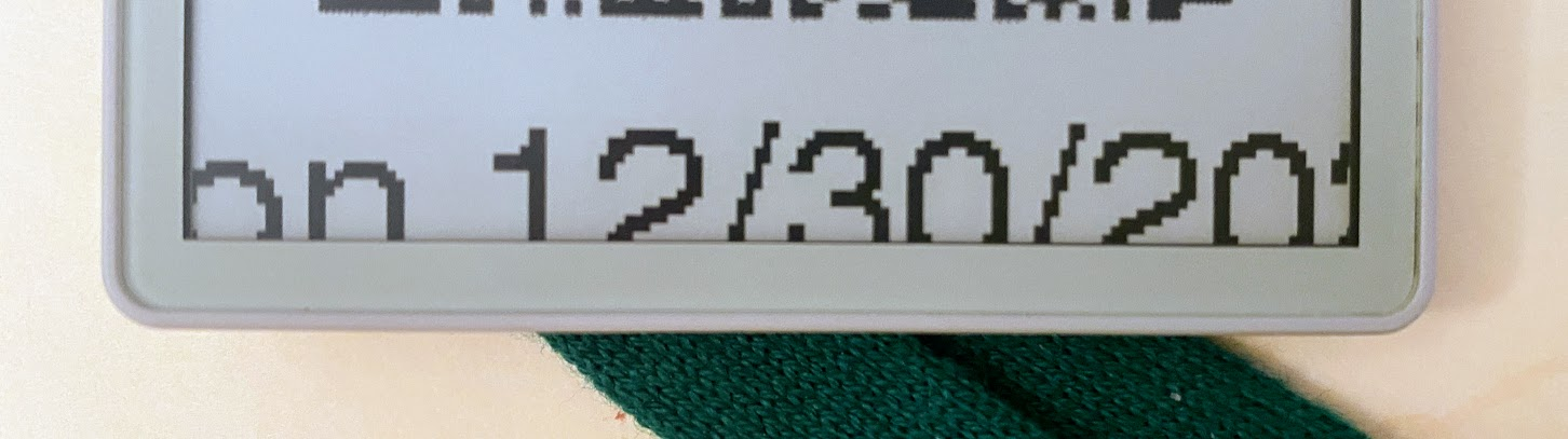
M5.Display.setFont(&fonts::Font4);
M5.Display.setTextSize(2.0);

Not sure if this is a bug or a feature, but it works!