This was caused by a missing double quotation mark in a file name in an "Execute code" block.....
W
Offline
Best posts made by wsanders
-
RE: UIFlow "Invalid Syntax"?
-
RE: M5STACK STATION PORT CONNECTORS
You want UNbuckled "Grove" connectors to fit all M5Stack devices. For example, the M5StickC-Plus will accept both unbuckled and bucked connectors, but the Core2 will only accept an unbuckled connector. If you have the buckled type, you can always cut the clip off so it will fit.
Generically, these connectors are called "HY2.0-4P" although nearly all vendors sell them as "Grove".
There's no standard for the Vcc and logic levels! So make sure your devices match. M5Stack devices supply 5V on the red conductor, but the logic levels are 3.3V.
-
RE: M5StickC-Plus Buzzer not working
Using //https://101010.fun/iot/m5stickc-plus-firststep.html
for inspiration, we can upload this program:#include <M5StickCPlus.h>
void setup() {
M5.begin();
M5.Lcd.setTextSize(3);
M5.Lcd.setRotation(3);
M5.Lcd.setTextColor(TFT_ORANGE);
}void loop() {
M5.update();
soundTest();
}void soundTest() {
for (int tone=100; tone < 4000; tone=tone+50) {
M5.Lcd.fillScreen(BLACK);
M5.Lcd.setCursor(80, 50);
M5.Lcd.printf("%d", tone);
M5.Beep.tone(tone);
M5.Beep.update();
delay(200);
}
}According to my ears there is a definite peak about 2500 Hz, with frequencies under 250 Hz and over 3000 not audible. Your ears may vary .....
-
UIFlow: How to try/except for "Connect to Wifi"?
I am trying to get the program to ignore failure to connect to WiFi. I tried to place a Wifi Connect block inside a try/except (with a bogus SSID/password):
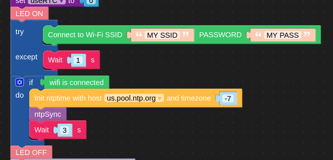
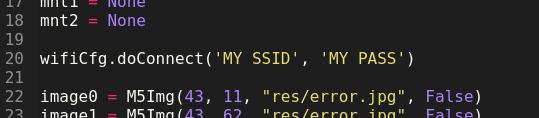
Instead, the program hangs, before the LED comes on, because the python that gets generated places the wifiCfg.doConnect up at the top of the program (line 20):
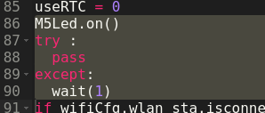
and the try/except block is empty, much later in the program at line 87:
Is there a way to create an exception for WiFi failure to connect?
I also notice that UIFlow does not have a "pass" block. I just put a wait() in mine - ???
-
RE: [SOLVED] Can't Run Paper S3 With BarGraph Example
I got the bar graph demo to work:
-
Using the latest M5 board package, you should see a board "M5PaperS3", so the requirement to downgrade the esp32 board package to 3.0.6 is not necessary. Use the "M5PaperS3" board definition instead of the generic ESP32S3 one.
-
The instructions to install epdiy are somewhat vague. Simply clone the epdiy library to your arduino library directory and it will work, doing a "make" is not necessary.
-
Follow the rest of the instructions at https://docs.m5stack.com/en/arduino/m5papers3/program, pay careful attention to the special board settings for OPI PSRAM, etc.
-
-
TZ magic in ESP/M5Unified
Mt RTC is set to UTC. Somehow, this magically works:
    setenv("TZ","PST8PDT",1);
    tzset();
    auto tm = localtime(&t);
    M5.Display.printf("ESP32 %04d/%02d/%02d (%s)  %02d:%02d:%02d\r\n",
          tm->tm_year+1900, tm->tm_mon+1, tm->tm_mday,
          wd[tm->tm_wday],
          tm->tm_hour, tm->tm_min, tm->tm_sec);
Just posting here in case someone is mystified by the Rtc.ino example, since it doesn't set the TZ "environment variable" the calls to localtime and gmtime will return the same.
-
RE: UIFlow: How to try/except for "Connect to Wifi"?
@wsanders SOLUTION: Use "Original Network Function" blocks instead.
-
RE: How to use "pushToSprite" in Core2
Isn't the method called pushSprite?
On a M5StickC-Plus, I use:
setup():
TFT_eSprite sgraph = TFT_eSprite(&M5.Lcd);
...
sgraph.createSprite(GRAPHW, GRAPHH);
...loop():
...
sgraph.pushSprite(TEXTW, 0);
.... -
RE: Anybody get drawJpgFile to work with M5 PaperS3?
Now that I think of it, I could not get drawJpgFile to work in a previous project (a fake Nixie watch), and I see from the PaperS3 demo program sample code that the Jpg is stored as a static array.
I got my simple badge display program to work by storing the image as a C array (exported from GIMP) and walking through the pixels, which is how I did it in my previous project. Suprisingly it's not incredibly slow but of course data in this format is incredibly bulky.
This github code is an example of how to convert a file into a statoc C array: https://github.com/notisrac/FileToCArray
In the next few days, maybe I'll figure out if SPIFFS works on the PaperS3 and report back.
-
Solution: Getting decent looking fonts on PaperS3
I'm trying to get decent-looking fonts on the PaperS3. As called by setFont, the fonts are huge and blocky (unaliased). However, If they are subsequently scaled by setTextSize, even wth a scale of 1.0, they are the right size and smooth.
You have to experiment. For example, with Font6 and Font8, punctuation charactersaren't rendered, I am guessing to save space. But Font4 scaled up to 2.0 looks very nice.
I've attached a couple of images that show this effect:
M5.Display.setFont(&fonts::Font4), without scaling:
M5.Display.setFont(&fonts::Font4);
M5.Display.setTextSize(2.0);
Not sure if this is a bug or a feature, but it works!
Latest posts made by wsanders
-
RE: [SOLVED} PaperS3 Touch Screen Latency
@wsanders This problem was caused by a reference to an uninitialized variable in that drawSomeTextOnScreen() function. As usual, the invalid reference caused weird behavior that was unrelated to the actual problem.
-
[SOLVED} PaperS3 Touch Screen Latency
I'm trying to make some progress on making the PaperS3 touch screen useful. I have the following code:
void loop(void)
{
    // necessary:
    M5.update();
    t = M5.Touch.getDetail(0);
    if (t.state > 0) {
      Serial.printf("Index:%d Count:%d IsPressed:%d Touch:%s\n",eventindex,eventcount,t.isPressed(), state_name[t.state]);
    }
    if (t.state == 14 || t.state == 10) {
      // on flick end or drag end
      drawSomeTextOnScreen();
    }
    delay(2);
}
The code properly detects the flick end or drag end event, but then there is about a 10 second delay before anything happens and the text is drawn on the screen.
Am I doing this right?
What is the device doing in the 10 seconds between the flick end or drag end and the time the screen starts to update?(FWIW delays in the loop of up to 50 msec seem reasonable. M5.Power.lightSleep disables interrupts and the device losts its mind (including serial output.) Does using the arduino delay call save any power anyway? )
The sample drawing program works fine, but it is just testing for t.isPressed():
void loop() { M5.update(); delay(20); t = M5.Touch.getDetail(); if (t.isPressed()) { M5.Display.fillCircle(t.x, t.y, 15, BLACK); } } -
RE: Anybody get drawJpgFile to work with M5 PaperS3?
@wsanders Bump. For future reference, the easiest way to get a static image into Arduino IDE code is to convert the image into an XBM with Gimp and use M5.Display.drawXBitmap. More here: https://github.com/wsanders/M5PaperS3-Stuff
-
RE: Board Manager 2.1.4 Failure in Arduino 1.8.19 IDE
@kuriko I believe so, but now that I've patched M5Unified, I'd need to unpatch and test again. I'll report back if anything further happens.
-
Board Manager 2.1.4 Failure in Arduino 1.8.19 IDE
M5Unfied version 0.2.7 installed. Do I need to use IDE 2 now? Trying to compile for PaperS3.
Workedaround by commenting out all references to M5StamPLC and M5Tab5 (some are bypassed by #ifdefs and don't have to be deleted):
Arduino: 1.8.19 (Linux), Board: "M5PaperS3, Disabled, OPI PSRAM, QIO 80MHz, 16MB (128Mb), Core 1, Core 1, Hardware CDC and JTAG, Enabled, Disabled, Disabled, UART0 / Hardware CDC, 16M Flash (3MB APP/9.9MB FATFS), 240MHz (WiFi), 921600, None, Disabled" /home/wsanders/Documents/ArduinoSketchbook/libraries/M5Unified/src/M5Unified.cpp:83:12: error: 'board_M5StampPLC' is not a member of 'm5::board_t' {aka 'lgfx::boards::board_t'} { board_t::board_M5StampPLC , GPIO_NUM_15,GPIO_NUM_13 , GPIO_NUM_1 ,GPIO_NUM_2 }, ^~~~~~~~~~~~~~~~ /home/wsanders/Documents/ArduinoSketchbook/libraries/M5Unified/src/M5Unified.cpp:148:12: error: 'board_M5StampPLC' is not a member of 'm5::board_t' {aka 'lgfx::boards::board_t'} { board_t::board_M5StampPLC , GPIO_NUM_7, GPIO_NUM_8, GPIO_NUM_9, GPIO_NUM_10 }, ^~~~~~~~~~~~~~~~ /home/wsanders/Documents/ArduinoSketchbook/libraries/M5Unified/src/M5Unified.cpp:167:12: error: 'board_M5StampPLC' is not a member of 'm5::board_t' {aka 'lgfx::boards::board_t'} { board_t::board_M5StampPLC , GPIO_NUM_21 }, ^~~~~~~~~~~~~~~~ /home/wsanders/Documents/ArduinoSketchbook/libraries/M5Unified/src/M5Unified.cpp: In member function 'void m5::M5Unified::_begin(const m5::M5Unified::config_t&)': /home/wsanders/Documents/ArduinoSketchbook/libraries/M5Unified/src/M5Unified.cpp:1237:19: error: 'board_M5StampPLC' is not a member of 'm5::board_t' {aka 'lgfx::boards::board_t'} case board_t::board_M5StampPLC: ^~~~~~~~~~~~~~~~ /home/wsanders/Documents/ArduinoSketchbook/libraries/M5Unified/src/M5Unified.cpp: In member function 'void m5::M5Unified::_begin_spk(m5::M5Unified::config_t&)': /home/wsanders/Documents/ArduinoSketchbook/libraries/M5Unified/src/M5Unified.cpp:1554:21: error: 'board_M5StampPLC' is not a member of 'm5::board_t' {aka 'lgfx::boards::board_t'} case board_t::board_M5StampPLC: ^~~~~~~~~~~~~~~~ /home/wsanders/Documents/ArduinoSketchbook/libraries/M5Unified/src/M5Unified.cpp: In member function 'virtual void m5::M5Unified::update()': /home/wsanders/Documents/ArduinoSketchbook/libraries/M5Unified/src/M5Unified.cpp:1821:21: error: 'board_M5Tab5' is not a member of 'm5::board_t' {aka 'lgfx::boards::board_t'} case board_t::board_M5Tab5: ^~~~~~~~~~~~ /home/wsanders/Documents/ArduinoSketchbook/libraries/M5Unified/src/M5Unified.cpp:1953:19: error: 'board_M5StampPLC' is not a member of 'm5::board_t' {aka 'lgfx::boards::board_t'} case board_t::board_M5StampPLC: ^~~~~~~~~~~~~~~~ /home/wsanders/Documents/ArduinoSketchbook/libraries/M5Unified/src/M5Unified.cpp: In member function 'void m5::M5Unified::setTouchButtonHeightByRatio(uint8_t)': /home/wsanders/Documents/ArduinoSketchbook/libraries/M5Unified/src/M5Unified.cpp:2044:19: error: 'board_M5Tab5' is not a member of 'm5::board_t' {aka 'lgfx::boards::board_t'} case board_t::board_M5Tab5: ^~~~~~~~~~~~ exit status 1 Error compiling for board M5PaperS3. This report would have more information with "Show verbose output during compilation" option enabled in File -> Preferences. -
RE: M5Unified 0.2.3 broken on PaperS3
Still a problem:
Arduino: 1.8.19 (Linux), Board: "M5PaperS3, Disabled, OPI PSRAM, QIO 80MHz, 16MB (128Mb), Core 1, Core 1, Hardware CDC and JTAG, Enabled, Disabled, Disabled, UART0 / Hardware CDC, 16M Flash (3MB APP/9.9MB FATFS), 240MHz (WiFi), 921600, None, Disabled"

/home/wsanders/Documents/ArduinoSketchbook/libraries/M5Unified/src/M5Unified.cpp: In static member function 'static bool m5::M5Unified::_speaker_enabled_cb_atomic_echo(void*, bool)':
/home/wsanders/Documents/ArduinoSketchbook/libraries/M5Unified/src/M5Unified.cpp:338:10: error: variable 'spk_cfg' set but not used [-Werror=unused-but-set-variable]
     auto spk_cfg = self->Speaker.config();
          ^~~~~~~
/home/wsanders/Documents/ArduinoSketchbook/libraries/M5Unified/src/M5Unified.cpp: In static member function 'static bool m5::M5Unified::_microphone_enabled_cb_atomic_echo(void*, bool)':
/home/wsanders/Documents/ArduinoSketchbook/libraries/M5Unified/src/M5Unified.cpp:441:10: error: variable 'spk_cfg' set but not used [-Werror=unused-but-set-variable]
     auto spk_cfg = self->Speaker.config();
          ^~~~~~~
cc1plus: some warnings being treated as errors
Multiple libraries were found for "WiFi.h"
 Used: /home/wsanders/.arduino15/packages/m5stack/hardware/esp32/2.1.3/libraries/WiFi
 Not used: /home/wsanders/arduino-1.8.19-NOSAVE/libraries/WiFi
exit status 1
Error compiling for board M5PaperS3.
M5GFX is now 0.2.5, M5United is 0.2.3, this bug comes from M5United, upgraded M5GFX is OK.
Too busy today to file a bug report on this, later.
-
M5Unified 0.2.3 broken on PaperS3
My sketches all fail to compile. I am using the 1.8.19 IDE on Linux, haven't moved to the 2.0 IDE yet :
Arduino: 1.8.19 (Linux), Board: "M5PaperS3, Disabled, OPI PSRAM, QIO 80MHz, 16MB (128Mb), Core 1, Core 1, Hardware CDC and JTAG, Enabled, Disabled, Disabled, UART0 / Hardware CDC, 16M Flash (3MB APP/9.9MB FATFS), 240MHz (WiFi), 921600, None, Disabled"

In file included from /home/wsanders/Documents/ArduinoSketchbook/libraries/M5Unified/src/M5Unified.h:5,
                 from /home/wsanders/Documents/ArduinoSketchbook/M5/badgeWX/badgeWX.ino:2:
/home/wsanders/Documents/ArduinoSketchbook/libraries/M5Unified/src/M5Unified.hpp: In member function 'virtual void m5::M5Unified::begin(m5::M5Unified::config_t)':
/home/wsanders/Documents/ArduinoSketchbook/libraries/M5Unified/src/M5Unified.hpp:326:62: error: no matching function for call to 'm5gfx::M5GFX::init_without_reset(bool&)'
       bool res = Display.init_without_reset(cfg.clear_display);
                                                              ^
In file included from /home/wsanders/Documents/ArduinoSketchbook/libraries/M5GFX/src/M5GFX.h:22,
                 from /home/wsanders/Documents/ArduinoSketchbook/libraries/M5Unified/src/M5Unified.hpp:19,
                 from /home/wsanders/Documents/ArduinoSketchbook/libraries/M5Unified/src/M5Unified.h:5,
                 from /home/wsanders/Documents/ArduinoSketchbook/M5/badgeWX/badgeWX.ino:2:
/home/wsanders/Documents/ArduinoSketchbook/libraries/M5GFX/src/lgfx/v1/LGFXBase.hpp:1411:10: note: candidate: 'bool lgfx::v1::LGFX_Device::init_without_reset()'
     bool init_without_reset(void) { return init_impl(false, false); };
          ^~~~~~~~~~~~~~~~~~
/home/wsanders/Documents/ArduinoSketchbook/libraries/M5GFX/src/lgfx/v1/LGFXBase.hpp:1411:10: note:   candidate expects 0 arguments, 1 provided
Multiple libraries were found for "WiFi.h"
 Used: /home/wsanders/.arduino15/packages/m5stack/hardware/esp32/2.1.3/libraries/WiFi
 Not used: /home/wsanders/arduino-1.8.19-NOSAVE/libraries/WiFi
exit status 1
With 0.2.2 I needed to use these includes, in this order:
#include <epdiy.h>
#include <M5Unified.h>
Maybe this has changed? Here's some sample code, it compiles with 0.2.2:
#include <epdiy.h> #include <M5Unified.h> static constexpr const char* state_name[16] = { "none" , "touch" , "touch_end" , "touch_begin" , "___" , "hold" , "hold_end" , "hold_begin" , "___" , "flick" , "flick_end" , "flick_begin" , "___" , "drag" , "drag_end" , "drag_begin" }; void setup(void) { Serial.begin(115200); M5.begin(); M5.Display.setRotation(M5.Display.getRotation() ^ 2); M5.Display.setEpdMode(epd_mode_t::epd_fastest); M5.Display.startWrite(); M5.Display.setTextSize(2); } void loop(void) { // too slow! M5.delay(10); M5.delay(2); M5.update(); // Count is going to be the bumber of "fingers" detected: 0, 1, max 2 // So, can be ignored for simple button press // Always seems to be 0 inside for loop? // auto count = M5.Touch.getCount(); auto t = M5.Touch.getDetail(0); if (t.state > 0) { // State is state of the entire touch screen // All we care about is t.wasFlicked Serial.print(t.state); Serial.println(state_name[t.state]); } M5.Display.display(); } -
What's the point of loopTask and appMain in ESP Arduino IDE?
Specifically, I am using a PaperS3. As I understand it, the Arduino IDE just runs all setup() and void() on one core unless you tell it otherwise. Or maybe the ESP library makes the Arduino IDE behave differently? AFAICT loopTask() and appMain() are used by the RTOS scheduler, so maybe the RTOS scheduler is installed by the Arduino IDE?
This code fragment is present in some sketches, like github.com/m5stack/M5Unified/blob/master/examples/Basic/Touch/DragDrop/DragDrop.ino:
#if !defined ( ARDUINO ) && defined ( ESP_PLATFORM ) extern "C" { void loopTask(void*) { setup(); for (;;) { loop(); } vTaskDelete(NULL); } void app_main() { xTaskCreatePinnedToCore(loopTask, "loopTask", 8192, NULL, 1, NULL, 1); } } #endif -
cfg.clear_display=false has no effect on PaperS3?
I might post this as a bug: cfg.clear_display = false seems to have no effect on the PaperS3. It would be useful to have it work because the device could be woken up without having to rewrite the whole screen. Perhaps this is a hardware limitation?
include <epdiy.h>
#include <M5Unified.h>

void setup() {
  auto cfg = M5.config();
  // This seems to have no effect:
  cfg.clear_display = false;
  M5.begin(cfg);
}
May ways to workaround for the time being.
-
RE: Icon on M5 paper
I would suggest formatting the icon as a XBM and the using drawXBitmap, no need to decode the bits yourself:
FOexample
#include "somexbm.h"
...
M5.Display.drawXBitmap(0, 0, xbm_bits, xbm_width, xbm_height, TFT_BLACK);
The .h file will have
#define xbm_width 540
#define xbm_height 960
static unsigned char xbm_bits[] = {
   0x00, 0x00, 0x00, 0x00, 0x00, 0x00, 0x00, 0x00, 0x00, 0x00, 0x00, 0x00, etc
You can easily produce an XBM file with GIMP or some other program. I don't remember the format, but I thiink the file is just a bitwise stream of pixels values.