No LoRa Gateway available ?
Check if you have coverage from the Helium Network ? You get some Data Credits (DC) for free for testing. 1'000'000 Data Credits will cost you $10 and will last for years. The Helium Network allows you transferring you data by MTTQ or Https , the same as with the TTN network. You can check if you have coverage in your area by chking the Helium map:
https://explorer.helium.com/ (There are still 350'0'00 Helium Gateways active thanks to all the guys trying to get "zero income" covering their expenses for the gateway) .
C
Offline
Posts
-
RE: Remote Sensing with Core2 (UIFlow) via LORA Point-to-point
-
RE: Arduino code for PaHuB2 + any I2C sensor
@teastain In Arduino you can uise the PCA9548 library .
Example : https://randomnerdtutorials.com/tca9548a-i2c-multiplexer-esp32-esp8266-arduino/ -
RE: UiFlow 2.0 discuss(how-to, bug, feature request or sometings)
@ajb2k3 ??? Using UIFlow or Python you can have multiple Apps or Programs on your M5Stack device !!
https://www.hackster.io/AJB2K3/multipage-programs-on-the-m5stack-core2-bc302c -
RE: Vibration Motor Question
Just hooked up the vibration motor to M5Core and had the same problems as you had ... The vibration motor went up to > 1 Amp and the M5Core went into brownout ...
I think the M5Stack Vibration Motor N20 uses the same schematic as the M5Stack N20 Propeller Unit ...
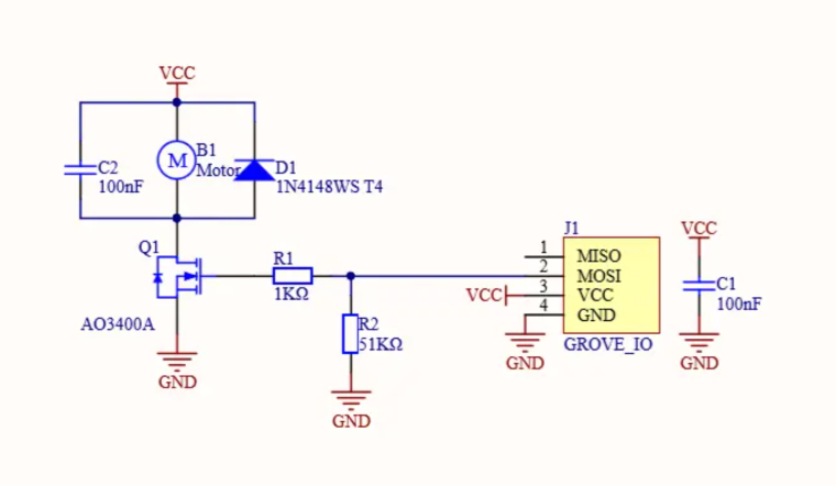
...i think the M5 Stack team screwed up with the resistors used for the control of the AO3400A mosfet :
R2 as a pull down resistor should be 10k Ohm instead of 51k Ohm !
R1 as a current limiting resistor schould be 200 Ohm - 1K Ohm -
RE: M5Stick with both Hat and Grove
Try putting the Wire1.begin(...) in your program loop instead of the setup {}. assigning other pins to the I2C channel;
Wire1.begin(32, 33, 100000UL); // for I2C TOF connection ..
before reading the TOF,
Wire1.begin(21, 22, 100000UL); // for I2C gyro connection ..
before reading the gyro. -
RE: SIM7080 Send HTML mail
Sending an email using HTML ???? The SIM7080 is only a internet modem . As with your computer connected to a moden you can then use the TLS channel and TLS protocols connected to your your mail server sending your e-mails.
Link using python: https://gist.github.com/jamescalam/93d915e4de12e7f09834ae73bdf37299
Link using arduino and ESP32: https://randomnerdtutorials.com/esp32-send-email-smtp-server-arduino-ide/ -
RE: M5Stick with both Hat and Grove
The ESP32 has only two I2C channels. Assigning Wire1to pins 0 and 26 you take away the standard I2C channel used for the gyro (pins 22 and 23). The easiest way would be: instead of using the HAT hook up both VL30X TOF Sensors to the grove connector. But you must change one of the sensors I2C address beforehand. Here is the the link to the arduino code assigning a new i2c address (standard 0x29) :
https://robojax.com/learn/arduino/?vid=robojax_VL53L0X_I2C_address.
Another possibilty would be using the M5Stack PaHub Unit as an I2C expander. -
RE: Scale accurate to 10g only
The M5Stack scale kit is intended making a human scale (up to 200 kg) and not one for a phone (210 g). Using the HX711 you have to choose the range of the weigh sensor (= load cell) according to your requirements:
- Range (10g, 200kg, xx tons ...)
- Precision class (C1,C2 .. C3 etc)
The M5Stack weigh sensors have an error rate of 0.3% full scale (Class C1) = +/- 600 grams.
I'm using weigh sensors class C3 measuring the weight of bee hives.
-
RE: M5 scales kit query
Addendum:
I will be testing different scale sensors monitoring the weight of bee hives and transmitting the data (MQTT, GPRS, LoRa, TTN, Helium, Sigfox?) and storing the data on a private server.
As a M5Stack enthusiast I will use their Cores and Atoms ideally suited for quick prototyping and proof of design.
You can look at and follow the progress of the project at
https://experiment.com/projects/participatory-research-to-explore-fungal-biodiversity-and-its-importance-to-bees. -
RE: M5 scales kit query
Incorrect readings ??? I never use a sensor without calibrating it... We had a discussion on that using the RGB sensor unit 3 years ago .... As we have a proverb in Germany :
Mist rein ---> Mist raus --- Garbage in --> garbage out. -
RE: M5STACK STATION PORT CONNECTORS
https://shop.m5stack.com/products/4pin-buckled-grove-cable:
Cables connecting the red grove port with units with a red grove connector (I2C),
connecting the black grove port with units with a black grove connector (digital, analog),
connecting the blue grove port with units with a blue grove connector (serial, RS432). -
RE: Don't know what to use
The RFID Unit is a I2C device. The scale unit isn't. Is uses a special protocol (using HX711 library). It will not work with the PbHub. As I mentioned in another community thread, you can get a I2C scale kit from DfRobot : https://wiki.dfrobot.com/HX711_Weight_Sensor_Kit_SKU_KIT0176.
DfRobot doesn't use the groove standard fot their wiring: VCC and GND are switched as well as the SDA and SCL lines.
Wish List for M5Stack: Make the scale kit I2C compatible by using the STM8/32 or AVR328 as they are using in the PbHub or 4Relay Unit making the compatible for the "universal" I2C bus. -
RE: ATOMIC PWM
@Livioch
Du setztest deine PWM Frequenz auf 100Hz entsprechend 10ms. Dann veränderst Du deine PWM Frequenz alle 10ms .... Da kommt natürlich nichts Gescheites mehr raus .. -
RE: RAW I2C Access help with SHT30 (ENVIII) please.
@ajb2k3
You can do everything in UIFlow !!
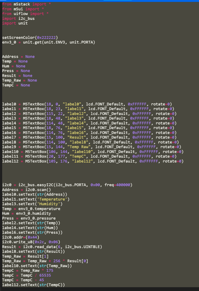
The first part of the sketch uses the M5Stack ENVII library and displays the values on a M5Stack core..
The second part uses pure I2C commands setting the SHT30 registers (0x2c,0x06) and then reads the 6 Raw data bytes into the "Result" list (temperature MSB, temperature LSB, temperature CRC, humidity MSB, humidity LSB, humidity CRC).
The the MSB and LSB temperature data are then converted to degrees Celsius accorfung to the SHT data sheet.
The corresponding Python Code looks like this:
-
RE: Wiring of M5Stack Mini Infrared Emitter & Receiver Unit
Yes, you have to "switch" the lines between the IR Unit and the Atom :
One side is Tx -> RX, the other side RX -> TX-
White line: IR Unit receives the signal and transmitts it(TX, marked "data" IN) ) to the Atom,. Atom is receiver (RX), (G32 as input)
-
Yellow line: Atom is the sender (TX) (G26 as output), IR Unit receives the data (RX) (marked "data" OUT) and transmitts the signal via IR (25Hz carrier) Check if it works with a mobile phone camera ...
-
-
RE: M5Stack同时可连接多少IO设备
Use the unit sensors with have a i2C connection. As long as they have different addresses you can hook up up to 127 different sensors/ actuators on the same bus. With the PaHub you can hook up 6 units having the same I2C address. For analog sensors you can use the PbHub ... So sticking to the I2C bus the limit of devices you can use is probably the power source you are using ......
-
RE: UHF RFID Unit(JRD-4035), ESP-wroom-32 and Micropython
Trying to read the UHF RFID without initializing all required parameters first (UHF Zone, Channel etc ..) will give you nothing back.
Try the UIFlow examples for the UHF RFID unit first. There you will find all the parameters you have to set for your country using the unit (https://www.gs1.org/sites/default/files/docs/epc/uhf_regulations.pdf) -
RE: Wifi settings tutorial
Using buttons and labels you can draw a screen table and use it as an on screen keyboard in order to enter the SSID and Password ..
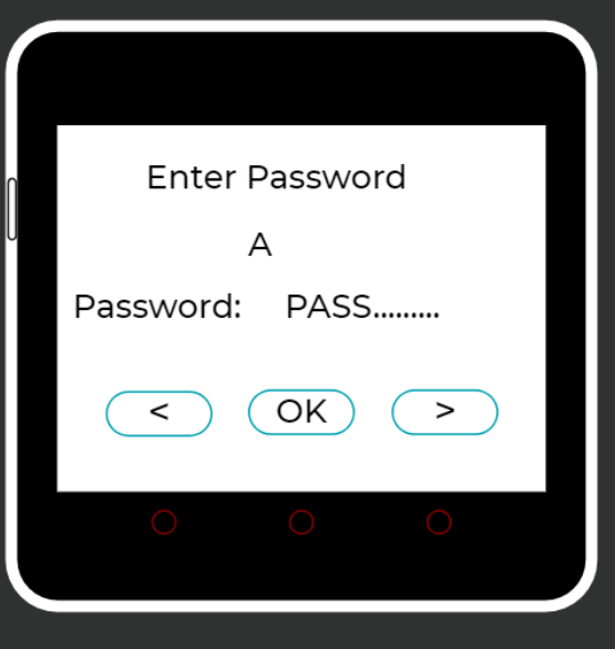
Pressing < > you scroll through the alphabet, with OK you confirm the letter... Much like setting and confirming your wifi credentials on an android TV
When finished you connect to the Wi-Fi with the SSID and Password. -
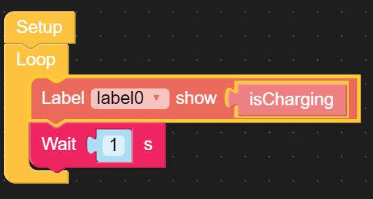
RE: UIFlow - Micropython - USB plugged in
You can use this function in UIFlow:
Whenever the USB is plugged in, the battery is charged.
You will find the block in the Hardware/Power section: