Navigation

    M5Stack Community

    • Register
    • Login
    • Search
    • Categories
    • Recent
    • Tags
    • Popular
    • Users
    • Groups
    • Search
    1. Home
    2. X-Dron
    X
    • Continue chat with X-Dron
    • Start new chat with X-Dron
    • Flag Profile
    • Profile
    • Following
    • Followers
    • Blocks
    • Topics
    • Posts
    • Best
    • Groups
    Save
    Saving

    X-Dron

    @X-Dron

    5
    Reputation
    9
    Posts
    3146
    Profile views
    0
    Followers
    0
    Following
    Joined Last Online

    X-Dron Follow

    Posts made by X-Dron

    • RE: GPS + GSM

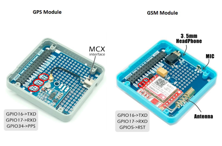
      Default the GPS and GSM modules are partially disconnected from the M5Stack bus.
      You must bridge the contact areas for connection.
      0_1524226964012_1524065523536-m5stack-gsm-and-gps-boards-gpios-used.jpg
      The GSM module has not alternatives for connection. It uses GPIO16 and 17 for UART and GPIO5 for reset.
      The GPS module has alternative connections. 16&17 or 1&3 or 5&13 for UART. If you d'not need a PPS-signal, you can not bridge it at all.
      BUT.
      GPIO 1&3 is used USB-UART (CP2104).
      I d'not know how to use GPIO 5&13 like a UART. This is not a typical application for ESP32.

      posted in FAQS
      X
      X-Dron
    • RE: External power to header ?

      @drwino
      :-)
      Good luck.

      posted in PRODUCTS
      X
      X-Dron
    • RE: External power to header ?

      @drwino
      I'm sorry for missprint. Of course pin "5V". :)
      I said the best and most problemless way is to use the usb connector of M5Stack. You could make a special USB cable only with 5V.
      All other methods have nuances.
      See M5-Core-Schematic.
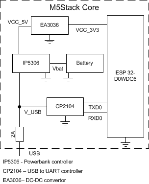
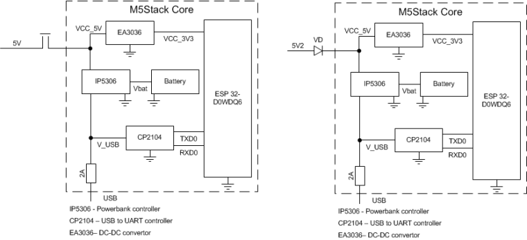
      The simplified power scheme looks like this.
      0_1523617639632_M5Stack2.png
      VCC_5V, VCC_3V3, Vbat are connected to the bus, V_USB is not.
      if you connect external power to VCC_5V then

      • A special USB programming cable with the USB 5V disconnected 'll not work. Course CP2104 is not powered.
      • If you want to program simply turn off the external power supply 5V. For example to use a jumper.
      • You can try to use a diode. But I do not have confidence.
      • The battery is not charged.
        0_1523617649260_M5Stack2_2.png
        I want to connect external 5V power to the V_USB wire and remove the USB-fuse.
        In this case all will powered and 5V from the USB is disconnected. Battery works too.
        All must have a common GND.
      posted in PRODUCTS
      X
      X-Dron
    • RE: How to connect DS18B20 - Which pins are available?

      Try it.
      GPIO2 fully free
      https://github.com/G6EJD/ESP32-DS18B20-Sensor-Reading

      posted in FAQS
      X
      X-Dron
    • RE: External power to header ?
      1. The easiest is to use the USB cable and connect the 5V to it.
        2.If you do not need a battery, you can connect to pin 5 on the bus.
        3.I'm going to use such a power scheme. Red lines are new wires.
        HPWR is not used in M5Stack now. it is presented only on the bus.
        0_1523562875175_M5Stack2.png
      posted in PRODUCTS
      X
      X-Dron
    • RE: Sim800l

      @jpilarski 在 Sim800l 中说:

      Is the mic on GPIO5

      No. mic and headphone are connected direct to SIM800L module.
      GPIO5 is reset.
      alt text
      Interconnection
      M5 Stask <> SIM800L
      Vbat - Vcc (3.7-4.3V)
      GPIO16(RX) - TXD
      GPIO17(TX) - RXD (must be not direct 3.3V > 2.5V)
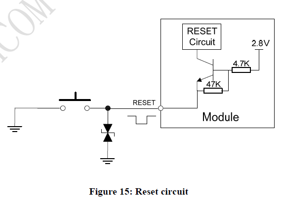
      GPIO5 - RST
      GND - GND

      RING is not used.
      DTR is not used.

      MIC+, MIC- to microphone.
      SPK+, SPK- to headphone.

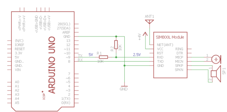
      Example for Arduino
      0_1523298952882_MIC_001.png
      0_1523298865995_09-04-2018 21-32-20.png

      posted in PRODUCTS
      X
      X-Dron
    • RE: Sim800l

      If you can Russian the best manual for SIM800L here
      http://codius.ru/articles/GSM_модуль_SIM800L_часть_1
      Many sketches for Arduino that can be easily conversion to M5 Stask.
      Just replace
      #include <SoftwareSerial.h>
      SoftwareSerial SIM800 (8, 9); // 8 - RX Arduino (TX SIM800L), 9 - TX Arduino (RX SIM800L)
      to

      HardwareSerial SIM800 (2); // pin 16 = RX, pin 17 = TX
      for example
      https://yadi.sk/d/SxWs6t0x3UBco6

      posted in PRODUCTS
      X
      X-Dron
    • RE: Review "LORA"

      Is this module compatible with Sim800L?
      Both use GPIO-5.

      posted in Lessons and Guides
      X
      X-Dron
    • RE: How to save data without SD card?

      use "Preferences" class
      #include <Preferences.h>

      Preferences preferences;

      void setup() {
      Serial.begin(115200);
      Serial.println();

      // Open Preferences with my-app namespace. Each application module, library, etc
      // has to use a namespace name to prevent key name collisions. We will open storage in
      // RW-mode (second parameter has to be false).
      // Note: Namespace name is limited to 15 chars.
      preferences.begin("my-app", false);

      // Remove all preferences under the opened namespace
      //preferences.clear();

      // Or remove the counter key only
      //preferences.remove("counter");

      // Get the counter value, if the key does not exist, return a default value of 0
      // Note: Key name is limited to 15 chars.
      unsigned int counter = preferences.getUInt("counter", 0);

      // Increase counter by 1
      counter++;

      // Print the counter to Serial Monitor
      Serial.printf("Current counter value: %u\n", counter);

      // Store the counter to the Preferences
      preferences.putUInt("counter", counter);

      // Close the Preferences
      preferences.end();

      // Wait 10 seconds
      Serial.println("Restarting in 10 seconds...");
      delay(10000);

      // Restart ESP
      ESP.restart();
      }

      void loop() {}

      posted in PRODUCTS
      X
      X-Dron