simple app Accu meter (MAX17043 module soldered inside Battery Module):
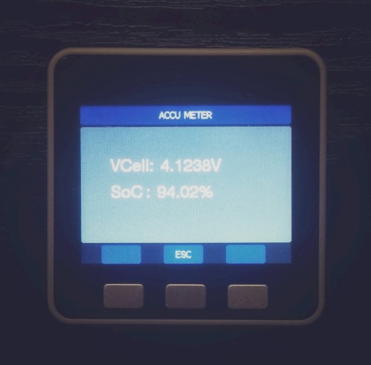
code based on nlamprian library from https://github.com/nlamprian/LiFuelGauge:
available on my gist:
https://gist.github.com/reaper7/c9f8dba68edae8c3d53075b10f6bbba4
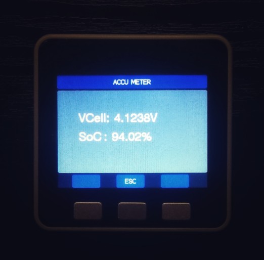
simple app Accu meter (MAX17043 module soldered inside Battery Module):
code based on nlamprian library from https://github.com/nlamprian/LiFuelGauge:
available on my gist:
https://gist.github.com/reaper7/c9f8dba68edae8c3d53075b10f6bbba4
@dda 在 Let's speed up DrawLine and DrawPixel? 中说:
Yep. And I managed to integrate this to the M5Stack library. I am doing tests, but so far so good. I've run a few modified sketches without issue. The TFT_ArcFill example is quite impressive.
.
.
.
There may be others, I'll see what happens when I compile the non-touch examples.
TFT_eSPI is the best lib, we added m5stack support some time ago:
https://github.com/Bodmer/TFT_eSPI/pull/88
btw, m5stack display lib based on the early version of TFT_eSPI
but since then, TFT_eSPI has developed a LOT!!!
P.S. for advanced GUI we also added m5stack support for GUIslice:
https://github.com/ImpulseAdventure/GUIslice/pull/34
which uses TFT_eSPI as display driver.
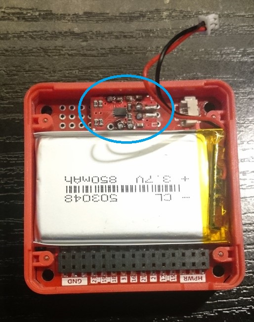
Accu meter app (MAX17043 module soldered inside Battery Module)
Names on the right side correspond to the GPIO numbers on the left and are connected together.
higher DA mean GPIO25
lower DA mean GPIO26
R0/T0 = GPIO3/GPIO1 -> uart0
R2/T2 = GPIO16/GPIO17 -> uart2
Similarly, bottom names applies to the gpio numbers at the top.

@m5stack - very good news!
P.S. please also check the quality of connectors, especially female (on master board),
maybe only my m5stack has such a problem but from the beginning of use, various pins have a contact problem
with bottom plates(I check different: ioExtension/proto board/battery board).
Evidently male pins from bottom plates do not have good contact with female connector on base plate, I do not check all contacts but have problem with accu pin, adc35 pin, adc36 pin.
it's very annoying and spoils the positive impression from the module
when you can not read the input status and wonder what is wrong in the code
and it's not the fault of the code but the lack of contact
P.S.P.S please also vote for this PR: https://github.com/espressif/arduino-esp32/pull/1242
because current version of board.txt do not include proper pins_arduino.h variant for m5stack and for e.g. ADC1 or ADC2 are unknown when compile
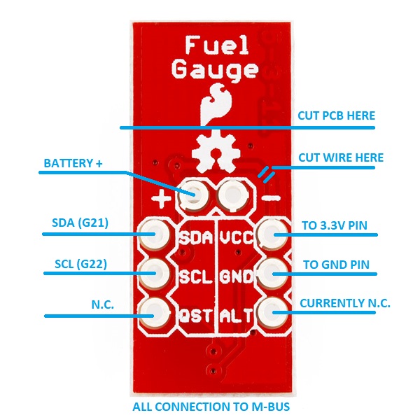
cutting pcb is not necessary,
cutting wire between ACCU+ and VCC also not necessary
but I do not want drain accu by max17043 when m5stack is off
REMEMBER! If wire between ACCU+ and VCC are not cut (on the max17043 pcb) as it is originally,
then connect only ACCU+ pin to M-BUS BATTERY and DO NOT connect VCC to M-BUS 3.3V
Hi @JimiT ,
Of course You can copy/clone/improve, this is for the people :)
About finally sketch size...there are two options:
Personally I use a second option to keep up with git changes.
BTW choose the partition size should be available in ide.
About sd loader...great idea! I didn't know this library, tnx for link!
from http://desire.giesecke.tk/index.php/2018/01/30/change-partition-size/
inside ..esp32\tools\partitions add new file for e.g. bigapp.csv with content:
# Name,   Type, SubType, Offset,  Size, Flags
nvs,      data, nvs,     0x9000,  0x5000,
otadata,  data, ota,     0xe000,  0x2000,
app0,     app,  ota_0,   0x10000, 0x1E0000,
app1,     app,  ota_1,   0x1F0000,0x1E0000,
eeprom,   data, 0x99,    0x3F0000,0x1000,
spiffs,   data, spiffs,  0x3F1000,0xF000,
and inside esp32\boards.txt add new(copy) board like:
##############################################################

m5stack_bigapp.name=M5Stack_bigapp

m5stack_bigapp.upload.tool=esptool
m5stack_bigapp.upload.maximum_size=1966080
m5stack_bigapp.upload.maximum_data_size=294912
m5stack_bigapp.upload.wait_for_upload_port=true

m5stack_bigapp.serial.disableDTR=true
m5stack_bigapp.serial.disableRTS=true

m5stack_bigapp.build.mcu=esp32
m5stack_bigapp.build.core=esp32
m5stack_bigapp.build.variant=esp32
m5stack_bigapp.build.board=M5Stack_bigapp

m5stack_bigapp.build.f_cpu=240000000L
m5stack_bigapp.build.flash_size=4MB
m5stack_bigapp.build.flash_mode=dio
m5stack_bigapp.build.boot=dio
m5stack_bigapp.build.partitions=bigapp

m5stack_bigapp.menu.FlashMode.qio=QIO
m5stack_bigapp.menu.FlashMode.qio.build.flash_mode=dio
m5stack_bigapp.menu.FlashMode.qio.build.boot=qio
m5stack_bigapp.menu.FlashMode.dio=DIO
m5stack_bigapp.menu.FlashMode.dio.build.flash_mode=dio
m5stack_bigapp.menu.FlashMode.dio.build.boot=dio
m5stack_bigapp.menu.FlashMode.qout=QOUT
m5stack_bigapp.menu.FlashMode.qout.build.flash_mode=dout
m5stack_bigapp.menu.FlashMode.qout.build.boot=qout
m5stack_bigapp.menu.FlashMode.dout=DOUT
m5stack_bigapp.menu.FlashMode.dout.build.flash_mode=dout
m5stack_bigapp.menu.FlashMode.dout.build.boot=dout

m5stack_bigapp.menu.FlashFreq.80=80MHz
m5stack_bigapp.menu.FlashFreq.80.build.flash_freq=80m
m5stack_bigapp.menu.FlashFreq.40=40MHz
m5stack_bigapp.menu.FlashFreq.40.build.flash_freq=40m

m5stack_bigapp.menu.UploadSpeed.921600=921600
m5stack_bigapp.menu.UploadSpeed.921600.upload.speed=921600
m5stack_bigapp.menu.UploadSpeed.115200=115200
m5stack_bigapp.menu.UploadSpeed.115200.upload.speed=115200
m5stack_bigapp.menu.UploadSpeed.256000.windows=256000
m5stack_bigapp.menu.UploadSpeed.256000.upload.speed=256000
m5stack_bigapp.menu.UploadSpeed.230400.windows.upload.speed=256000
m5stack_bigapp.menu.UploadSpeed.230400=230400
m5stack_bigapp.menu.UploadSpeed.230400.upload.speed=230400
m5stack_bigapp.menu.UploadSpeed.460800.linux=460800
m5stack_bigapp.menu.UploadSpeed.460800.macosx=460800
m5stack_bigapp.menu.UploadSpeed.460800.upload.speed=460800
m5stack_bigapp.menu.UploadSpeed.512000.windows=512000
m5stack_bigapp.menu.UploadSpeed.512000.upload.speed=512000

m5stack_bigapp.menu.DebugLevel.none=None
m5stack_bigapp.menu.DebugLevel.none.build.code_debug=0
m5stack_bigapp.menu.DebugLevel.error=Error
m5stack_bigapp.menu.DebugLevel.error.build.code_debug=1
m5stack_bigapp.menu.DebugLevel.warn=Warn
m5stack_bigapp.menu.DebugLevel.warn.build.code_debug=2
m5stack_bigapp.menu.DebugLevel.info=Info
m5stack_bigapp.menu.DebugLevel.info.build.code_debug=3
m5stack_bigapp.menu.DebugLevel.debug=Debug
m5stack_bigapp.menu.DebugLevel.debug.build.code_debug=4
m5stack_bigapp.menu.DebugLevel.verbose=Verbose
m5stack_bigapp.menu.DebugLevel.verbose.build.code_debug=5

##############################################################
then for your big apps you can select this board
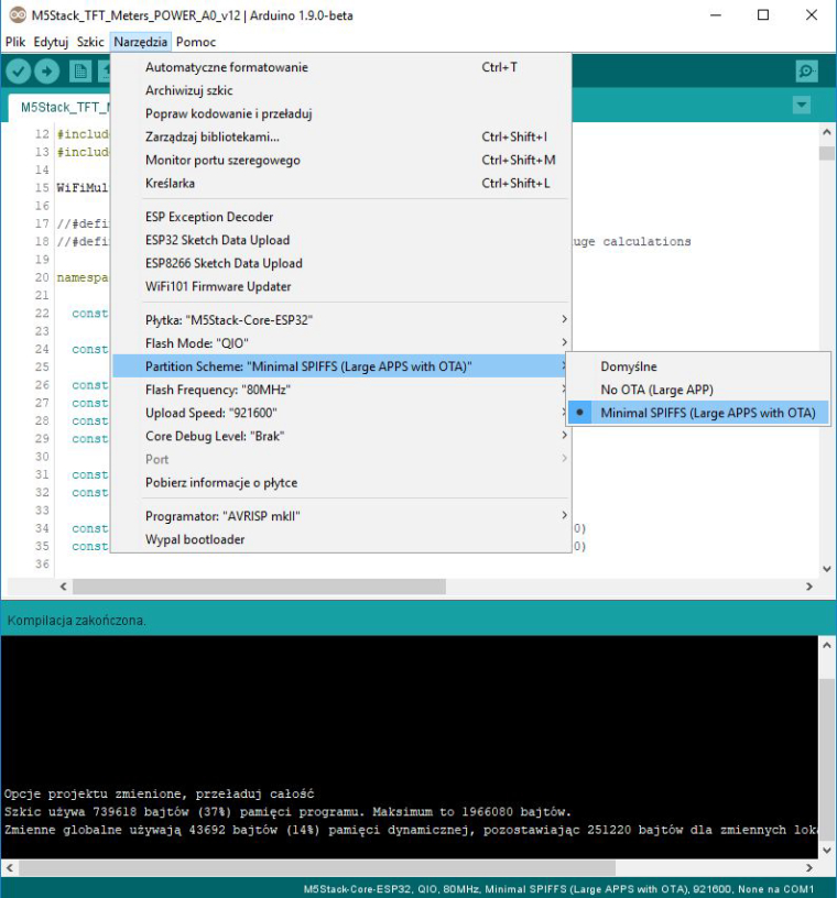
Finally we can choose partition scheme for M5Stack board in Arduino IDE.
It means that for large application (for eg. with bluetooth stack),
that exceededs the maximum flash size for the default partition scheme,
we can choose two others partitons "no ota" or "minimal spiffs".
https://github.com/espressif/arduino-esp32/pull/1382
https://github.com/espressif/arduino-esp32/pull/1302
maximum sketch size for partitions:
1310720 -> default
2097152 -> no_ota
1966080 -> min_spiffs
on Arduino, You are try something like this??:
Serial1.begin(115200, SERIAL_8N1, 32, 26);
pin32 and pin26 on grove connector as RX and TX
I haven't tested it...
I received M5StickC yesterday and I noticed a problem with the display in my M5Stick-C,
but additionally my Stick is completely unusable because the reset button is broken!
It did not work like the other buttons (with a characteristic click). I unscrewed the case and the parts of the button have come out.

Unfortunately I'm not happy with the winning.
How can I open the rest of the plate to replace the button? Is it possible?
I wrote to you in this case on the aliexpress.
what is your screen orientation? landscape or portrait ??
where is your text?
try to swap values 160 with 120 for portrait mode
or use this instead:
M5.Lcd.drawString("M5Stack has been connected", (int)(M5.Lcd.width()/2), (int)(M5.Lcd.height()/2), 2);
which calculates values for current orientation.
I do not have hw for tests
For safe use in the future, better way is:
void Display_WiFi_Connected() {
  M5.Lcd.clear(BLACK);
  M5.Lcd.setTextDatum(CC_DATUM);
  M5.Lcd.drawString("M5Stack has been connected", 160, 120, 2);
}
because drawCentreString is marked as deprecated
use:
setTextDatum(uint8_t datum);
https://github.com/m5stack/M5Stack/blob/master/src/utility/In_eSPI.h#L554
and available options:
https://github.com/m5stack/M5Stack/blob/master/src/utility/In_eSPI.h#L331
Phisically connect Your MAX to SPI lines and CS leave connected as is!
M5Stack pinout:
https://github.com/m5stack/M5Stack#pinout
MAX DO -> M5Stack MISO (GPIO19)
MAX CS -> M5Stack GPIO17
MAX CLK -> M5Stack CLK (GPIO18)
Looks like You have connection prepared corectly...
Change only Your sketch like this:
#include <SPI.h>
#include <Adafruit_MAX31855.h>
//#include <M5Stack.h>

// Example creating a thermocouple instance with software SPI on any three digital IO pins.
//#define MAXDO   19
//#define MAXCLK  18
#define MAXCS   17

Adafruit_MAX31855 thermocouple(MAXCS);

void setup() {
  //M5.begin();
  Serial.begin(115200);
  Serial.print("Internal Temp = ");
  Serial.println(thermocouple.readInternal());

  while (!Serial) delay(1); // wait for Serial on Leonardo/Zero, etc

  Serial.println("MAX31855 test");

  thermocouple.begin();

  // wait for MAX chip to stabilize
  delay(2000);
}

void loop() {

  // basic readout test, just print the current temp
  Serial.print("Internal Temp = ");
  Serial.println(thermocouple.readInternal());

  double c = thermocouple.readCelsius();
  if (isnan(c)) {
    Serial.println("Something wrong with thermocouple!");
  } else {
    Serial.print("C = ");
    Serial.println(c);
  }

  delay(1000);

  //M5.update();
}
@sibtcha , try to initialize Adafruit_MAX31855 library only with CS pin:
Adafruit_MAX31855 thermocouple(MAXCS);
as You see at library source: https://github.com/adafruit/Adafruit-MAX31855-library/blob/master/Adafruit_MAX31855.cpp
when You declare SPI CLK line then library try read this device by software SPI implementation!
also You are forgot thermocouple.begin();
Finally we can choose partition scheme for M5Stack board in Arduino IDE.
It means that for large application (for eg. with bluetooth stack),
that exceededs the maximum flash size for the default partition scheme,
we can choose two others partitons "no ota" or "minimal spiffs".
https://github.com/espressif/arduino-esp32/pull/1382
https://github.com/espressif/arduino-esp32/pull/1302
maximum sketch size for partitions:
1310720 -> default
2097152 -> no_ota
1966080 -> min_spiffs
Names on the right side correspond to the GPIO numbers on the left and are connected together.
higher DA mean GPIO25
lower DA mean GPIO26
R0/T0 = GPIO3/GPIO1 -> uart0
R2/T2 = GPIO16/GPIO17 -> uart2
Similarly, bottom names applies to the gpio numbers at the top.