A component designator only makes sense if you have the correct schematic.
P
Offline
Posts
-
RE: PCB Reference Designators Documentation
-
RE: m5stack ToF vl53l0x unit will stop scanning I2C devices
@vvs551 Could you make a picture of the TOF PCB? The schematics are not yet available
I have a hypothesis on all this I2C issuses.But before just to exclude software bugs, please check to use the latest ESP32 Arduino core, at least V1.0.1 https://github.com/espressif/arduino-esp32/releases including all the recent I2C fixes.
-
RE: Grove HUB unit trouble
@vvs551 If you wire the ENV module to the GROVE port A (with and without HUB) do you have the charging base connected?
Specifically do you have the M5GO Base (e.g. Fire) or the Core Bottom Base? -
RE: PCB Reference Designators Documentation
@lukasmaximus that document, which is heavily outdated
-
RE: HOWTO: M5Stack Fire - use the full 16MB with the Arduino IDE (UPDATED)
@Kabron
Install the github repository. The Arduino ESP32 v1.0.0 release version does not recover from failed reads on the I2C bus until the power is cycled.
Don't know what is the purpose of multiple power management ICs if you have only one battery. But the registers of this IP 5306_I2C are similar to the IP5108 covered in http://forum.m5stack.com/post/1464
Maybe to prevent the battery charging during boot is a workaround -
RE: Ideas, helping M5Stack document stuff...
@watson
M5Fire schematics?
Its fine to used the altered pin maps as basis but be aware your leaflets contain errors.
Fire has an undocumented I2C device on the bus, most probably the power management IC.M5Camera really I2C SDA on G22 not G25? Schematics?
M5Core
Not up to date, connectors missingM BUS
HPWR? -
RE: HOWTO: M5Stack Fire - use the full 16MB with the Arduino IDE (UPDATED)
@kabron
Have you installed the gitlab repository code or the release version https://github.com/espressif/arduino-esp32/releases ?
Because the v1.0.0 Release has a huge I2C bug that affects all readings on the bus and is only corrected in the repository -
RE: Ideas, helping M5Stack document stuff...
@ajb2k3
The forum is hosted by Alisoft (Alibaba group) in Hangzhou behind the great firewall. So something might trigger the behavior (keywords) intentional or not. The main site is hosted in Singapore and not affected. -
RE: Ideas, helping M5Stack document stuff...
There is also this very weird behavior, that http://forum.m5stack.com is giving a timeout error from my IP address in the last week after I posted something here for 3 times. Well certainly coincidence, most certainly.
After renewing my dynamic IP this forum loads immediately. -
RE: Ideas, helping M5Stack document stuff...
I abandoned this platform for commercial prototypes because of lack of documentation. But at least there are now hints for more info in a new repository.
https://github.com/m5stack/M5-Schematic -
RE: PIN number and shields
Well, the confusions epicenter is at M5stack team, it is not your fault @fameuhly
The programming pin list in Arduino is
static const uint8_t TX = 1;
static const uint8_t RX = 3;
static const uint8_t TXD2 = 17;
static const uint8_t RXD2 = 16;
static const uint8_t SDA = 21;
static const uint8_t SCL = 22;
static const uint8_t SS    = 5;
static const uint8_t MOSI  = 23;
static const uint8_t MISO  = 19;
static const uint8_t SCK   = 18;
static const uint8_t G23 = 23;
static const uint8_t G19 = 19;
static const uint8_t G18 = 18;
static const uint8_t G3 = 3;
static const uint8_t G16 = 16;
static const uint8_t G21 = 21;
static const uint8_t G2 = 2;
static const uint8_t G12 = 12;
static const uint8_t G15 = 15;
static const uint8_t G35 = 35;
static const uint8_t G36 = 36;
static const uint8_t G25 = 25;
static const uint8_t G26 = 26;
static const uint8_t G1 = 1;
static const uint8_t G17 = 17;
static const uint8_t G22 = 22;
static const uint8_t G5 = 5;
static const uint8_t G13 = 13;
static const uint8_t G0 = 0;
static const uint8_t G34 = 34;
static const uint8_t DAC1 = 25;
static const uint8_t DAC2 = 26;
static const uint8_t ADC1 = 35;
static const uint8_t ADC2 = 36;
However, M5Stack team decided to name the pins in the limited info differently in different places. 13 on the pin header and the proto module is G13 but it is not routed to the core module edge pins. I am really wondering why they did two SPI connectors on opposite sides, but forgot the mandatory chip select pin? At least G2 and G5 have the same colour.
You can try with G16 and G17 on a Core (not on Fire - PSRAM!) because most likely you wont need the second UART.
-
RE: Power on 5V pin when switched off
There is also some info here but due too the lack of an adequate documentation of this Chinese junk nothing can be granted. There is no up to date schematic, maybe the power management chip is controllable or not.
Anyway, because of the support situation of M5Stack I switched in prototyping to another WROVER module board both personally and at work. Documentation is a prerequisite and not an optional extra.
-
RE: PIN number and shields
I have a step motor driver TB6600, I use the following arduino sketch by connecting the PIN 2, 5 and 8 on the Arduino Nano.
// defines pins numbers
const int stepPin = 5;
const int dirPin = 2;
const int enPin = 8;void setup() {
// Sets the two pins as Outputs
pinMode(stepPin,OUTPUT);
pinMode(dirPin,OUTPUT);
pinMode(enPin,OUTPUT);I would like to use the same thing on the m5stack but I can not find the good PIN.
Include right libraries and use a stepmotor library with non blocking code (interrupt driven, so you can update the display, play sound etc.). Anyway for a quick test you can modify your code. Here I use pin 13, but there are many free pins.
#include <M5Stack.h>
const int stepPin = 5;
const int dirPin = 2;
const int enPin = 13;//add this to setup
void setup() {
m5.begin();
pinMode(stepPin,OUTPUT);
pinMode(dirPin,OUTPUT);
pinMode(enPin,OUTPUT);M5.Lcd.clear(BLACK);
M5.Lcd.setTextColor(RED);
M5.Lcd.setTextSize(2);
M5.Lcd.setCursor(65, 10);
M5.Lcd.println("STEPMOTOR");
M5.Speaker.mute();//add this to loop
void loop() {
m5.update();Connect ground, Pin 2, 5, 13 with your driver. However, because the M5stack is 3.3V the signal level might be too low for your driver expecting 5V and you need a level converter.
-
RE: Mod to programmatically disable speaker whine/hiss.
@Calin Hold your ear on the "mute" speaker. There is still noise with your code.
THX for the hardware mod suggestion.
-
RE: m5stack camera module - hardware design bug
Well, because of lack of documentation you are on your own.
The demo example lists
Pin Configuration
CONFIG_D0=32
CONFIG_D1=35
CONFIG_D2=34
CONFIG_D3=5
CONFIG_D4=39
CONFIG_D5=18
CONFIG_D6=36
CONFIG_D7=19
CONFIG_XCLK=27
CONFIG_PCLK=21
CONFIG_VSYNC=22
CONFIG_HREF=26
CONFIG_SDA=25
CONFIG_SCL=23
CONFIG_RESET=15The big question is: Is the BME280 and MPU6050 soldered on the board (as you indicated)? Is the I2C SDA of the BME280 physically connected to G22 as the leaflet says or G25?
For me unsoldered peripherals is very suspicious. It smells like big hardware bug. If M5Camera with PSRAM based on WROVER module uses really G22 for the I2C and also connects this pin as VSYNC to the cam the bug is obvious.
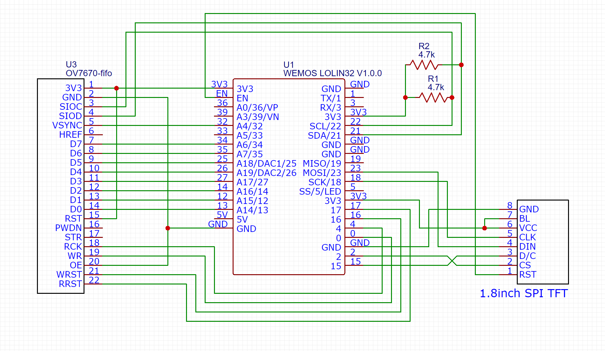
A proper design is with I2C pullups. Here is an example from bitluni
-
RE: M5ez, a complete interface builder system for the M5Stack as an Arduino library. Extremely easy to use.
Tested M5ez-demo on a Fire. Compiled with Arduino 1.8.7 with PSRAM=enabled. No issue, no Neopixel, no crackling sound during boot, everything flawlessly.
Also the OTA Update worked. Maybe the user should try the included OTA application and exclude compiling errors by flashing your github binary? -
RE: HOWTO: M5Stack Fire - use the full 16MB with the Arduino IDE (UPDATED)
Further info:
Partition tables are documented in the esp idf:
https://docs.espressif.com/projects/esp-idf/en/latest/api-guides/partition-tables.htmlRAM
ESP32 has 512 kB RAM. This is divided into IRAM (instruction RAM), DRAM (data RAM), and RTC memory.
From the Rechnical Reference pp25 only 328 kB is available as SRAM in two blocks. So 320kB is reasonable. I assume it is only used as an indicator in Arduino for the RAM percentage. PSRAM is only switched on or off, there is no check of size involved. -
RE: m5stack camera module - hardware design bug
@ajb2k3
This is not true.
The M5Stack ESP32 Camera Module is using a OV2640 with a "hack" of the I2S interface because this ESP32 subsystem is able to DMA for the data. The camera control is over the Serial Camera Control Bus (SCCB) protocol that is using I2C routines. Additionally the GROVE connector makes the I2C accessible for peripherals.
The M5Stack ESP32 WROVER with PSRAM Camera Module additionally has the BME280 and MPU6050 on a second I2C.But who knows? Still there are no up to date schematics. I mean something with the actual wiring of the PCB. Not the overview picture. Which is btw only posted on Aliexpress:

My opinion: It is a silly idea to share the camera VSYNC and SIOC with the BME280 and MPU6050.