Hi,
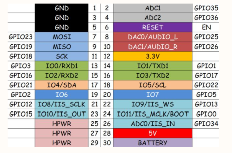
being an owner of several Core, Atom and Stick I've had a good run so far with M5Stack products, and used them both for personal use and for work, but I'm now going to use other ESP32-based products in the future unless JTAG is added as a debugging interface in the next releases.
Already having to manage my own ESP-IDF build chain because Arduino is the """most powerful"""" option out there that you can get out of the box is frustrating enough, since the Arduino framework is objectively both bloated and lacking in features, and this issue should warrant an entry of its own in the Wish List; but also having to debug with countless printfs is a nightmare.
Let me be clear on this: you will NOT see any PROFESSIONAL environment debugging its devices via any printf() or .Print() whatsoever: if you need to inspect memory in search of overflows, runtime errors, memory leaks and so on, doing it without a proper debugging interface like JTAG is nearly impossible (and no, sorry, GDBstub does not fit the bill).
It's very disappointing to see this issue left completely ignored by the M5Stack team, seeing as well that a lot of the devices are marketed towards "industrial use", so please, PLEASE do leave the JTAG interface intact and broken out so people can use your products as full fledged devices and not just educational toys!!

