Use :
void GT911::updateB()						// as update but modify by Bricox ...
{
    r814E.reads = read(0x814E);				// "read struct" AND these 5 explicite bits fields
    if(r814E.status)
    {
        if(r814E.touchPts != 0)
        {
            _is_finger_up = false;
            _num = r814E.touchPts;			// "_num" could be definitively replaced by "r814E.touchPts"
            uint8_t data[num * 8];
            read(0x8150, data, _num * 8);	// read block of all fingers , up to 5*8 bytes
            for(int j = 0; j < _num; j++)	// for each finger
            {
                uint8_t *buf = data + j * 8;// address base of each finger
Sorry, comments that were aligned, in my notepad++ by multiple Tabs, are no longer aligned in the snippets viewer
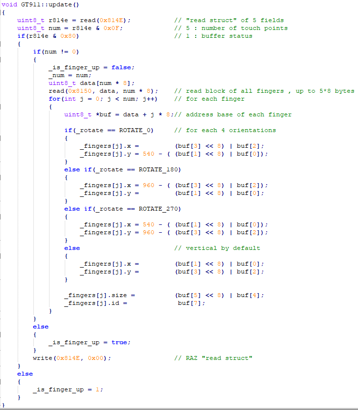
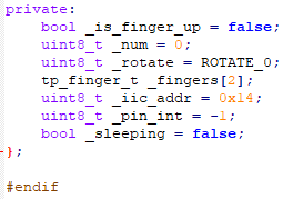


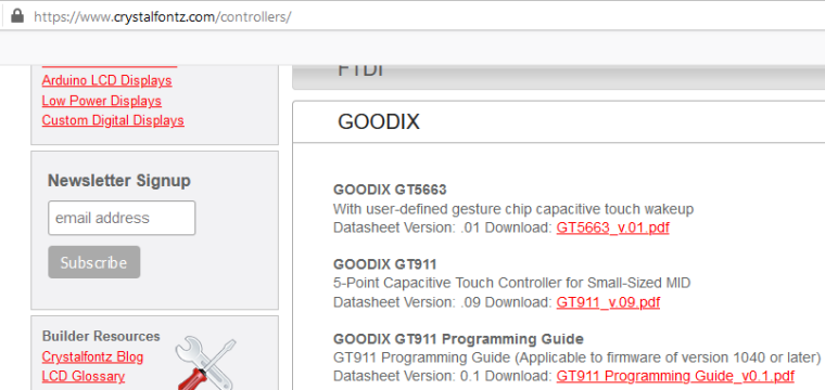
 The Google search with this image did not succeed.

