Hello,
I completed the schema with VUSB_IN, VSYS and OR fonction with D9,D12

SYL
Hello,
I completed the schema with VUSB_IN, VSYS and OR fonction with D9,D12

SYL
Hello,
On mine, the maxi level indicator of charge is 86% corresponding to 4.18V
I measured USB current with the program "Factory test" and a serial USB device named "UT25".
The value is 131 mA, without interraction.
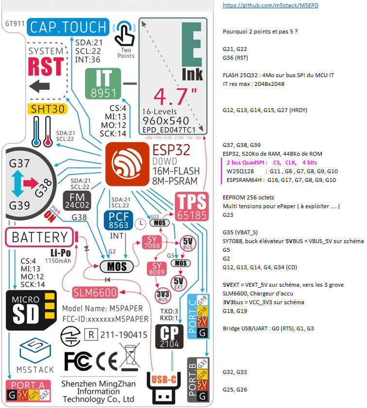
I also wrote personal comments about all GPIOs (in french, my native language):

All GPIOs are represented (except non-existent ones : 20, 24, 28, 29, 30, 31)
SYL
@felmue
Indeed GPIO36 is only input.
So I looked for another GPIO used only as input to reverse the 2 GPIO on the pcb.
I found the GPIO27 which tells ESP32 that the IT8951 is ready for a SPI dialogue
IT_SPI_HRDY (schema)
#define M5EPD_BUSY_PIN 27 (M5EPD.h)
EPD.begin(M5EPD_SCK_PIN, M5EPD_MOSI_PIN, M5EPD_MISO_PIN, M5EPD_CS_PIN, M5EPD_BUSY_PIN); (M5EPD.cpp)
m5epd_err_t M5EPD_Driver::begin(int8_t sck, int8_t mosi, int8_t miso, int8_t cs, int8_t busy, int8_t rst)
_pin_busy = busy;
pinMode(_pin_busy, INPUT);

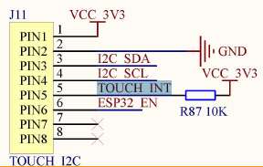
On my pcb, the resistance R87 is absent (unwelded)
All you have to do is reverse the 5 and 16 tabs on the ESP32.
I scraped the varnish and then scanned the pcb.
You have to cut the 2 tracks between the 2 pins of the esp32 and the 2 vias.
then solder 2 thin wires.
Use :
void GT911::updateB()						// as update but modify by Bricox ...
{
    r814E.reads = read(0x814E);				// "read struct" AND these 5 explicite bits fields
    if(r814E.status)
    {
        if(r814E.touchPts != 0)
        {
            _is_finger_up = false;
            _num = r814E.touchPts;			// "_num" could be definitively replaced by "r814E.touchPts"
            uint8_t data[num * 8];
            read(0x8150, data, _num * 8);	// read block of all fingers , up to 5*8 bytes
            for(int j = 0; j < _num; j++)	// for each finger
            {
                uint8_t *buf = data + j * 8;// address base of each finger
Sorry, comments that were aligned, in my notepad++ by multiple Tabs, are no longer aligned in the snippets viewer