Making a Robot: USB-C -> ATOM -> 2x SERVO2 ?
-
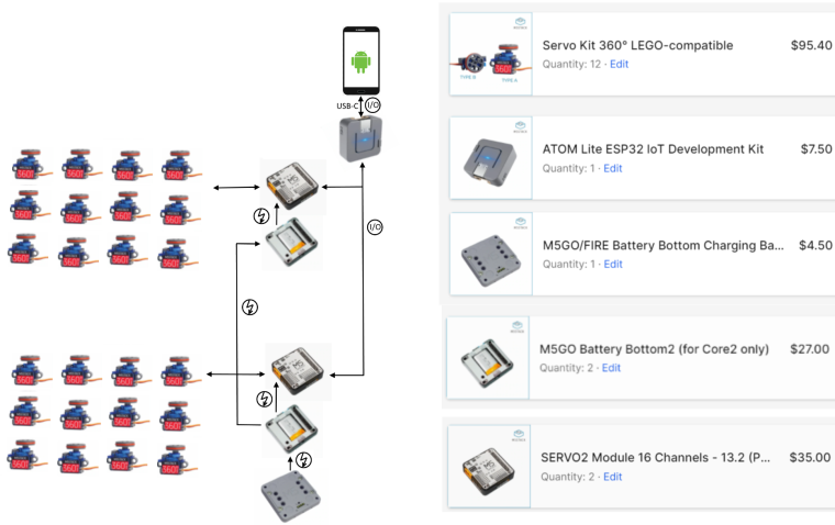
@ajb2k3 Looks very nice, gives me hope that it is all is possible in the end. The SERVO2-Module i thought is intended to control multiple servos. Here is some paint-work of the intended setup:
-
@schlabbermampf - Your picture shows 12 servos being driven from one battery. That's a lot if they are all running at the same time. You might be able to get away with that if only one servo moves at a time and they have no static load. But otherwise you will need to give some serious thought to a big battery with thick wires and serious connectors.
-
@paulhdietz thank you that's surely something to consider! i may also think about reducing the total amount of servos as well.
-
@schlabbermampf ATOM lite is not compatible with CORE M5stack modules. It is preferable to use a CORE M5FIRE or M5GO
-
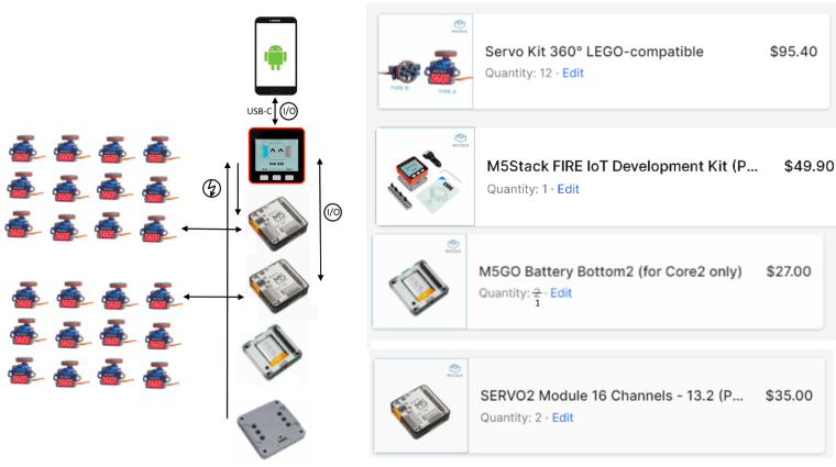
@Arno thats good to know ;D i imagined one could wire the ATOM and SERVO2s together anyway to pipe the signals. But having a CORE seems fine too so here is the new setup:

its great that the FIRE does have a Battery-Bottom already and i assume this is a very basic setup now. maybe it would be more straight forward to make a single stack but making two interconnected stacks like in the image is surely possible.
Maybe removing the Battery-Modules and get the power right instead. (Though i really like the magnetic charging-connector ;)
-
The Atoms are not directly compatible as the bases and modules are 54X54mm and use the 30 pin MBus where as the atom is only 20x20mm and uses the Atom expansion port.
That said the modules communicate using I2C and can be driven but you would need to alter the I2C address of each module to use have separate address and separate power supplies as 24 servos will cause brownouts (I get brownouts with only 6 servos if I don't use a separate power supply. If you change the I2c address' they can be stacked together and use only one external power supply.
-
@ajb2k3 yes makes sense, thats what the SERVO2 module shop-description says, i just get it to understand slowly ;D (just discovered the Documentation of all the M5 parts!) since i like to use the 360° servos with speed and direction control via PWM it may be possible to ensure (in software) a limit for the applied power in total.
Looks like bridging the 30 pin MBus over some short distance with a cable is kinda overkill so a single stack it shall be.
Power management strongly depends on what the servos have to lift, so overall weight-balance/efficiency of all parts is what its all about then in the long term (even when plugged into a full power source).
So i want to get my hands on these pieces soon and start digging. happy to share some progress here :D
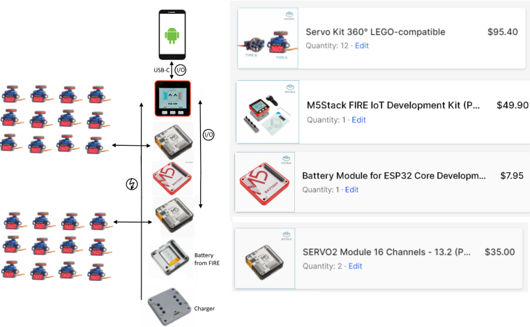
Thanks for your kind and fast replies :Dedit: here is the stack, quite simple. (hope these servos do not fry to soon):
-
@schlabbermampf You can delete the M5GO Bottom2 battery from your shopping list, it is reserved for CORE2 and you already have a battery in the M5Stack FIRE pack.
-
@Arno yes, i can remove the battery-bottom from the FIRE module, put the SERVO2 module instead and attach the battery at the bottom (to use the charger). just thought: to have each SERVO2 has its own power supply (maybe using more SERVO2+Battery modules with each less servos attached?)
-
Hello @Schlabbermampf
just to be clear. The servos attached to the SERVO2 module will not be powered from the Battery Module (or the battery bottom of the FIRE). The Battery Module will only power the M5Stack device.
The SERVO2 module has a separate VBAT_2 line which is not connected to the VBAT of the Battery Module or M5Stack device. Check the schematic here. Subsequently the magnetic charger will only charge the battery for the M5Stack.
You'll need to attach a separate battery to the SERVO2 module directly at the DC INPUT (6 - 12V) using the provided thick wired cable. And it probably will need substantially more capacity than the 500mAh of the Battery module anyways. One servo has a rated Locked rotor current of about 750mA and your battery needs to drive 12 of them. See specification here.
And you'll have to charge the battery for the servos with an external charger.
I would probably start w/o the battery for the servos and initially power them through an external power supply. With that setup you could measure the DC current of the working robot and then depending on how long it should run from battery decide on the size and capacity of the battery. (Which will add additional weight to the robot.)
Thanks
Felix -
@felmue Thank you for your kind answer! Since the shop description of the SERVO2 states: "When the battery base is used for power supply, the maximum output power is 5V / 2A." So it sounds like its possible in general but realistically to drive 1 or 2 servos at a time? or do i miss the point? i understand that the Battery-Module is way to weak to power all the servos at once.
-
@schlabbermampf said in Making a Robot: USB-C -> ATOM -> 2x SERVO2 ?:
@ajb2k3 yes makes sense, thats what the SERVO2 module shop-description says, i just get it to understand slowly ;D (just discovered the Documentation of all the M5 parts!) since i like to use the 360° servos with speed and direction control via PWM it may be possible to ensure (in software) a limit for the applied power in total.
Looks like bridging the 30 pin MBus over some short distance with a cable is kinda overkill so a single stack it shall be.
Power management strongly depends on what the servos have to lift, so overall weight-balance/efficiency of all parts is what its all about then in the long term (even when plugged into a full power source).
So i want to get my hands on these pieces soon and start digging. happy to share some progress here :D
Thanks for your kind and fast replies :Dedit: here is the stack, quite simple. (hope these servos do not fry to soon):
You will need to add a 200ms wait at the end of the program loop (or was it 500ms) to slow down the command transmissions otherwise they will fry (I have learned that the hard way after killing 3!)
As @felmue stated, the battery packs will not power the servos, the servos will only be powered from the external supply. If you try, the Fire will suffer from "Brown outs" and keep resetting when more then a few try to operate.
-
@ajb2k3 okay makes sense somehow, so it is dangerous to change the commands to the servos with a very high frequency. That makes it of course harder to just run a single servo at a time xP
But in general it sounds reasonable to control 12 servos but power only 1 at a time with a battery-module? -
Hello @Schlabbermampf
looking at the schematics I don't see a path from the 5V the M5Stack device provides to the outputs of the servos. I think that statement "When the battery base is used for power supply, the maximum output power is 5V / 2A". is wrong. Also a little below there is another statement "The module must use the external power supply of DC interface when driving the servo." which contradicts the first one.
That said, I don't own this particular module so I cannot say for sure what is correct and what not.
Thanks
Felix -
@felmue thank you for clearing this up! the schemantics are surely to trust!
taking a look at the "PLEN5Stack DIY Small Bipedal Robot" it uses a custom "Control-Board" to connect the servos, and has also a custom battery plugged into (1500 mAh)... 8 servos are though an optimistic number -
okay lets try this setup. from the descriptions it seems to be perfect for a robotic-arm. so just need 6 of these. interconnecting them in a row using the Port.B and Port.C plugs on the Motion-board and Grove cables.
in software the servo-controls get piped from the usb-connection down the Ports through all the ATOMs.
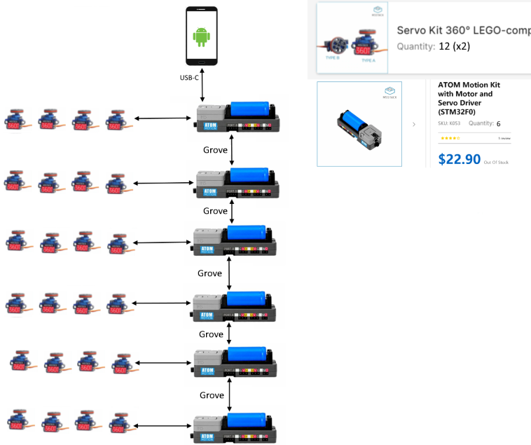
Maybe this sounds reasonable. Sadly the ATOM Motion Kit is currently Out of Stock
edit: in case the servo-controls can not be passed easily/quickly though the row-connection (e.g. the data needs to be received and sent by each ATOM with major delay), it may make sense to connect them using a PaHUB2 and an additional ATOM for parallel distribution?
-
On one hand things are going great and i'm learning a lot on the way.
On the other hand i realized that reading the Position of a servo, like it is shown in the Arduino example-code of the Motion Kit, is not sufficient as sensory-data (it just represents the applied position/velocity). Due to physical interaction i want to track the real, measured angle to compare with the desired.
So in the long run i'll use servos with Position-Feedback to read the angle from the additional wire. As noob its hard to compare any specs, but the "KST MR320 PF" may be appropriate as replacement (still confused about the min and max angle it can take, it must not turn infinite, but a range of at least 270° would be great).
For the current prototyping, i will extend each servo with an Angle-Module (potentiometer), combined with a PbHub and connected to the Motion-Kit. This may be a bit overkill (in cables and weight), but cheaper and sufficient to have a nervous-system as processing-inputs.
-
Your setup sounds doable! The ATOM Lite ESP32 can control two SERVO2 modules (12 servos each) without major issues, but powering 24 servos may require careful battery and power management. Using separate battery modules with a single charging base is smart—just ensure proper wiring and charging circuits. For streaming camera data over USB-C, the ATOM Lite might struggle; upgrading to an ESP32-C3 or Core might be better. LEGO framing is a great idea for prototyping! Start small, test servo control and power, then scale up step by step.
-
Hello @hacxx
sorry, but I do not understand why you would reply to a post three years later. It just doesn't make sense to me.
Plus an M5Atom Lite doesn't stack well with any module as it doesn't have the M5Stack bus.
Thanks
Felix
Hello! It looks like you're interested in this conversation, but you don't have an account yet.
Getting fed up of having to scroll through the same posts each visit? When you register for an account, you'll always come back to exactly where you were before, and choose to be notified of new replies (either via email, or push notification). You'll also be able to save bookmarks and upvote posts to show your appreciation to other community members.
With your input, this post could be even better 💗
Register Login