🤖Have you ever tried Chat.M5Stack.com before asking??😎
  • Modules for M5 StickC Plus2

    2
    0 Votes
    2 Posts
    2k Views
    robskiR
    @jakeycodesstuff what cards? RFID? then you need RFID unit.
  • M5Stack GRBL 13.2 Module serial connection

    4
    0 Votes
    4 Posts
    2k Views
    N
    Just to clarify my motivation: I would like to upgrade the Module firmware to GRBL1.1 instead of 0.8 I would like to communicate with the Module from a raspberry pi via raw serial commands and not the high level I2C Library provided by M5
  • PAHub revival

    5
    0 Votes
    5 Posts
    3k Views
    felmueF
    Hello @DR_Froggy_rD I am afraid that doesn't work. A PaHub is for i2C devices (red Grove connector); the PDM unit is an I2S device (white Grove connector). BTW: that is the reason in UIFlow2 PaHub doesn't show as option when the PDM unit selected. Thanks Felix
  • CoreS3 and Goplus2

    4
    0 Votes
    4 Posts
    2k Views
    felmueF
    Hello @rammelsberg I don't see solder jumpers and I cannot find the source code for the firmware running in M5GoPlus2 so no, I don't think you can easily modify the I2C address. Thanks Felix
  • LoRa (433 old) LoRa V1.1

    6
    0 Votes
    6 Posts
    4k Views
    felmueF
    Hello @s1y99 ok, now I understand - thank you for clarifying about the closed source M5Core firmware. BTW: for RST and IRQ you could set no jumper and then solder a wire each to the desired GPIO on the M5Stack bus connector. Thanks Felix
  • 0 Votes
    1 Posts
    1k Views
    No one has replied
  • 4-20 mA Unit with wemos S2 mini ESP32

    17
    0 Votes
    17 Posts
    9k Views
    robskiR
    @obstbauer TBH if you are using M5Stack modules/units with not M5Stack controllers maybe its worth to have at least one M5Controller (atom?stick? )to be able to check module functionality
  • Tailbat problem: black connector ph2.0-4p

    2
    0 Votes
    2 Posts
    1k Views
    ajb2k3A
    @LeBagh No, the housing clips over the contacts and is held to the PCB only by the contact pins. It is not a normal header but it is a 2.0mm header not a 2.96mm header
  • M5 Stamp C3 -> Which Flash Mode to choose in Arduino IDE

    2
    0 Votes
    2 Posts
    4k Views
    PaulskptP
    @Knobsi Hi, your question is already two years old. I guess you'll have found the answer, however I just came across it today. I want to share with you an experience I had yesterday: Suddenly I encountered a problem after upgrading the Arduino IDE from v2.3.4 to v2.3.5. The board that I use is an M5 Atom Echo which has an ESP32-PICO processor. After compiling and building a sketch, that compiled, built, and ran OK with v2.3.4, It crashed after compiling and building and running with v2.3.5. In the crash report I saw "DIO". In Arduino v2.3.5 I checked the setting: > Tools > Flash Mode. I saw that the Flash Mode was set for: "QIO". After I changed the setting Flash Mode it to DIO, re-compiling and building, the sketch ran OK. Regards, @Paulskpt
  • MIDI Synth Unit with DIN & TRS connectors (SAM2695)

    4
    0 Votes
    4 Posts
    3k Views
    E
    @holofloh Connecting TXD to RXD & supplying 5V to the Grove connector works great! I never thought about studying the schematic right on the device. Thanks for your assistance!
  • 8-Channel Servo Driver Unit to drive a 5 volt DC motor

    1
    0 Votes
    1 Posts
    1k Views
    No one has replied
  • M5 GNSS module magnetometer false reading

    1
    0 Votes
    1 Posts
    1k Views
    No one has replied
  • LLM module. how to mute? all methods failed

    2
    0 Votes
    2 Posts
    2k Views
    S
    @s00pa 我也遇到了相同的问题哪怕是查看了源码依旧找不到为何会发出声音
  • 0 Votes
    1 Posts
    1k Views
    No one has replied
  • Issues w/ 4EncoderMotor

    4encodermotor
    4
    4
    0 Votes
    4 Posts
    3k Views
    C
    Thanks for the tips @felmue 🙂. I think I found a working recipe. My conclusions would be the following: 
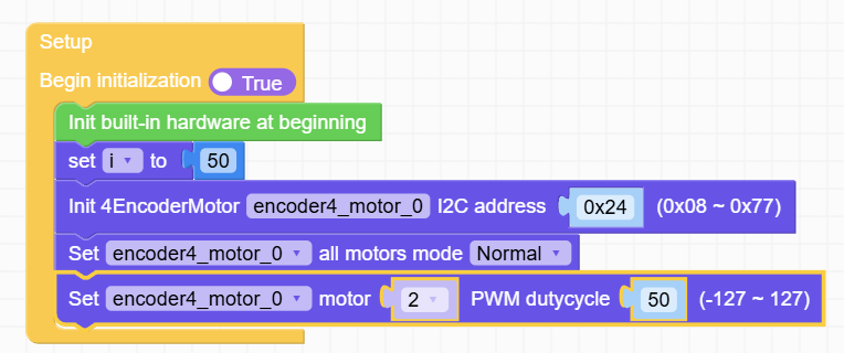
1/ For my motor, I am using P, I, D = 1, 0, 0. I think an even lower P coef would have worked, but the API doesn't accept it. 2/ W/ this values, I reach the maximum speed w/ speed =~30. Then if I decrease the wanted speed, the actual speed decreases as well. When I arrive at -14, the actual spin is 0. Decreasing more will make the motor turn the opposite direction. 3/ I find this negative value odd. I don't understand why it's offseted from 0. 4/ If I go the opposite direction, i.e. -50 and increase, the stop point is not -14 any more. It's about -3. So there is some kind of hysteresis effect. 5/ I'd say that the reduction of my gearbox (1:50) corroborated w/ the resolution of the encoder, pushes the PID params to the low limit. 6/ The position mode works similar to the position. However, when arriving at the set point, the motor oscillates (a lot if high speed; a bit, if low speed). So for me is no go to use this, although my use case does involve stopping at position. I'll use the speed + control it via the program; i.e. decrease it when approaching the target. 7/ I don't understand why the PWM mode oscillates. In my opinion it's a bug. I don't think the PWM mode should have used the feedback of the encoder. So all in all, I'll be able to continue my project now. 🙂
  • Trouble w/ Stepmotor Driver Module v1.1 & UiFlow2

    2
    1
    0 Votes
    2 Posts
    2k Views
    C
    My findings: 1/ I needed to switch this to disable (or eliminate the line). Really curious. You give the command "please enable", and it does the opposite. In my opinion this is a bug. I'm pretty sure we are talking about a bug. I.e. that boolean is somehow interpreted negated. My question is the following: how can I use precise movement? I'm pretty sure the answer is NO (using this lib). I struggled a bit and wrote myself some code. But I ended using another lib. More info in this post.
  • LLM Module

    14
    0 Votes
    14 Posts
    9k Views
    ajb2k3A
    @Snyder_br Yes, you have to remove the bottom plate/battery to connect modules.
  • Exploring the LLM Module with Core3

    3
    1 Votes
    3 Posts
    3k Views
    ajb2k3A
    @dsrc12 Thanks for the update, I have been too busy of late to even consider ordering an LLM let alone know what to do with one.
  • PM2.5 Demo not starting up

    5
    1
    0 Votes
    5 Posts
    4k Views
    M
    I have the same issue. Sensor runs with easyloader example. Did anybody solved it? Could it be, that pins are not assigned correctly with uiflow? there is a matching table on the docu web page, where pins should be assigned according the controller you use. But how can I change pin assignment in a uiflow example?
  • Issues with Stepmotor Driver Module v1.1 (HR8825) Using M5Stack

    5
    0 Votes
    5 Posts
    4k Views
    V
    Kind of an old thread but I wanted to respond since it may help others who are trying to get this module to work, not much out there on the Arduino coding side. I believe the issue might be the pin assignment for step and dir, it's actually printed on the PCB. For the Core2 X, Y, Z step = 13, 27, 2 and dir = 14, 19, 0 respectively. So I'm not sure why STEP_PIN is set to 15, maybe this is the legacy Core? I used the same referenced Stepmotor code (https://github.com/m5stack/M5Module-Stepmotor) and did get it working eventually. Here is some very basic example code that may help: #include <M5Unified.h> #include "Module_Stepmotor.h" // change to CORE2 if using Core2 #define CORE_S3 #ifdef CORE_S3 static const int X_STEP_PIN = 18; static const int X_DIR_PIN = 17; static const int Y_STEP_PIN = 6; static const int Y_DIR_PIN = 7; static const int Z_STEP_PIN = 13; static const int Z_DIR_PIN = 0; static const int SDA_PIN = 12; static const int SCL_PIN = 11; #elif defined CORE2 static const int X_STEP_PIN = 13; static const int X_DIR_PIN = 14; static const int Y_STEP_PIN = 27; static const int Y_DIR_PIN = 19; static const int Z_STEP_PIN = 2; // Not sure about this one static const int Z_DIR_PIN = 0; static const int SDA_PIN = 21; static const int SCL_PIN = 22; #endif static Module_Stepmotor driver; void setup() { Wire.begin(SDA_PIN, SCL_PIN, 400000UL); driver.init(Wire, 0x27); driver.resetMotor(0, 0); driver.resetMotor(1, 0); driver.resetMotor(2, 0); driver.enableMotor(1); // PWM, sets the speed of the stepper motor, adjust accordingly ledcSetup(0, 500, 8); // XYZ step ledcAttachPin(X_STEP_PIN, 0); ledcAttachPin(Y_STEP_PIN, 0); ledcAttachPin(Z_STEP_PIN, 0); ledcWrite(0, 127); // XYZ dir pinMode(X_DIR_PIN, OUTPUT); digitalWrite(X_DIR_PIN, 1); pinMode(Y_DIR_PIN, OUTPUT); digitalWrite(Y_DIR_PIN, 1); pinMode(Z_DIR_PIN, OUTPUT); digitalWrite(Z_DIR_PIN, 1); } void loop() { digitalWrite(X_DIR_PIN, 0); delay(2000); digitalWrite(X_DIR_PIN, 1); delay(2000); }