šŸ¤–Have you ever tried Chat.M5Stack.com before asking??šŸ˜Ž
  • Hello & how do I report a memory leak in the TPU?

    1
    0 Votes
    1 Posts
    524 Views
    No one has replied
  • LLM Module USB-C port & USB hub

    1
    0 Votes
    1 Posts
    576 Views
    No one has replied
  • M5Stamp C3 - I2C interface

    7
    0 Votes
    7 Posts
    13k Views
    P
    @felmue @mlindholm I recently had the same problem with I2C on an M5STAMP C3U. The appropriate solution seems to be the @mlindholm one, but its sample code was a bit incomplete Here is a working example in the context of a DS3231 RTC A TwoWire structure needs to be inititalised specifically, then referenced by the used I2C library (if any ; RTC library in my case). No need for pullup resistor (in my case) #include <Wire.h> // Declare alternate I2C pins #define I2C_SDA 5 #define I2C_SCL 4 // Setup the TwoWire instance (static memory !) TwoWire I2CM5 = TwoWire(0); void setup () { ... // Initialise the TwoWire instance I2CM5.begin(I2C_SDA, I2C_SCL, 400000); // Ask the library to use this setting // (most I2C libraries accept a TwoWire object as argument of begin) rtc.begin(&I2CM5); ...
  • Unit MIC with K131 (Air Quality Kit (ESP32‑S3)

    1
    0 Votes
    1 Posts
    610 Views
    No one has replied
  • 4 Relay Card Failure

    1
    0 Votes
    1 Posts
    418 Views
    No one has replied
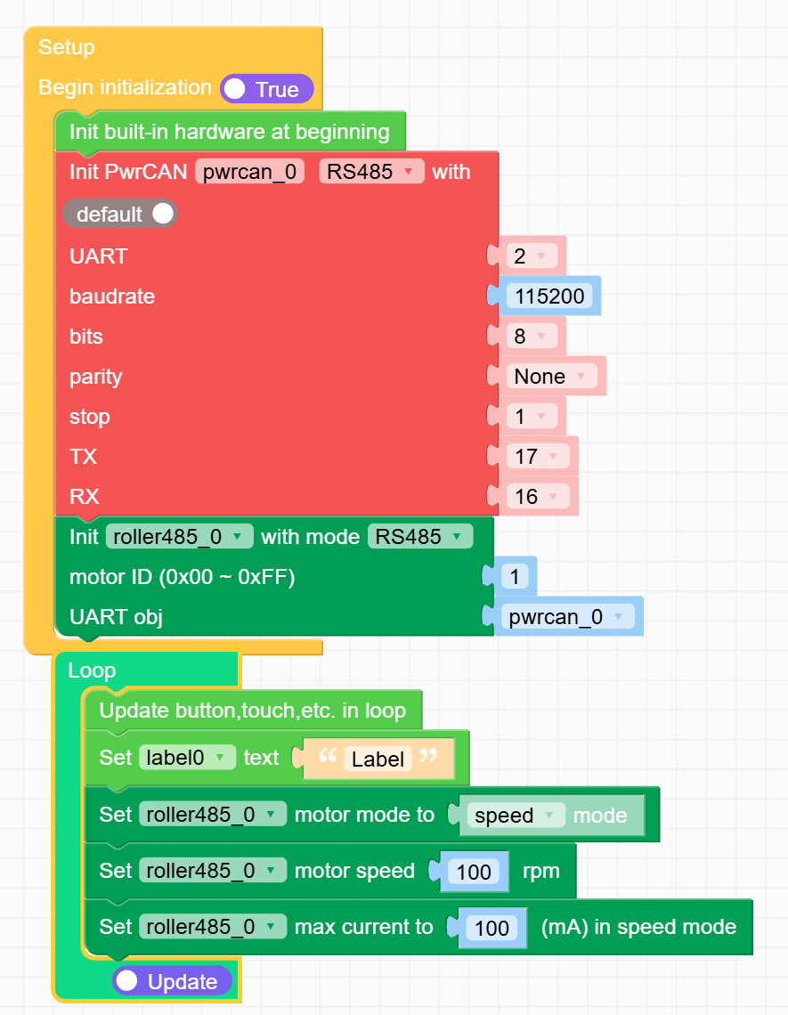
  • Roller485 with PWRCAN and CORE

    3
    1
    0 Votes
    3 Posts
    1k Views
    H
    @iorex I’ve had partial success using the Roller485 with the pwrCan module. Your setup looks similar to mine, except I’m using a Core3, so my pin numbers are different. First, check whether your motor is in RS485 mode. The screen on the back should show COM: 485. Second, make sure the motor ID is set to 1. The third line on the motor screen should read ID: 0x01. Lastly, confirm that the motor’s baud rate is 115200 (this is the default). If all of the above is correct, you can move on to the pwrCan module. Did you flip the resistor for RS485 to the ON position? Are the DIP switches configured correctly? I was able to control motor speed over RS485, but I still get the error: ā€œUnexpected response length: 32, expected: 17.ā€ It looks like there’s a communication issue from the motor back to the pwrCan module. As an alternative, you can power the motor using the power pins on the RS485 terminal and send commands via I²C. It requires more wiring, but it works with much less hassle.
  • PPS module and touchscreen

    3
    0 Votes
    3 Posts
    916 Views
    B
    @felmue That did it! Thanks a lot!
  • 0 Votes
    1 Posts
    508 Views
    No one has replied
  • "Brake mode" for motor driver in ATOMIC MOTION

    atom motion
    1
    0 Votes
    1 Posts
    588 Views
    No one has replied
  • Battery Module 13.2 - 2nd battery connector function?

    1
    0 Votes
    1 Posts
    435 Views
    No one has replied
  • Increase the sample rate for UWB sensor

    uwb sensors core2
    1
    0 Votes
    1 Posts
    585 Views
    No one has replied
  • oDrive soft upgrade

    1
    0 Votes
    1 Posts
    645 Views
    No one has replied
  • Unit MIDI: MIDI_IN to AUDIO_OUT?

    2
    0 Votes
    2 Posts
    953 Views
    E
    @dov I think I ran in to the same thing if I understand your question. See if this post helps. It works for my situation https://community.m5stack.com/topic/7458/midi-synth-unit-with-din-trs-connectors-sam2695?_=1760294339690
  • Help with 4in8out module - Core2

    1
    0 Votes
    1 Posts
    609 Views
    No one has replied
  • LAN-W5500 restarts instead of "TCP data receive"

    1
    0 Votes
    1 Posts
    605 Views
    No one has replied
  • Goplus2 DC input

    1
    0 Votes
    1 Posts
    662 Views
    No one has replied
  • HBridge Unit works in forward, but not in reverse?

    1
    0 Votes
    1 Posts
    730 Views
    No one has replied
  • Trying to get this LoRa Module working on Core2

    7
    1 Votes
    7 Posts
    3k Views
    H
    @felmue Dear Felix, Actually, we have done nearly the same thing. We have connected this module: HopeRF RFM95W to the connectors on the back of the Core2. That works great. We have no idea why the LoRa module does not work with the Core2. Maybe a SPI conflict somewhere deep in the background, maybe a power issue or maybe, and more likely, we are lacking some understanding. Anyway, we have decided to use a Proto board, solder the LoRa module on it and place that on the backside of the Core2. We have to do that for 35 devices, but it is fail save. Thanks for all the effort Regards
  • M5Stack 4IN8OUT connectors

    2
    0 Votes
    2 Posts
    2k Views
    robskiR
    @martincollett said in M5Stack 4IN8OUT connectors: M5Stack 4IN8OUT those are not usual ones [image: 1758003924007-2pterm0.png] [image: 1758003924022-2pterm.png]
  • 0 Votes
    1 Posts
    1k Views
    No one has replied