HOWTO: M5Stack with GPS, GSM and LoRa, all at the same time
-
I have gotten all three radio boards to work with the M5Stack at the same time. This was a little more involved than it needs to be because documentation is either missing, not all in the same place or (in one case) apparently wrong. I'll use this post to document what I did and I have added a sketch that tests for complete functionality of the boards. I'll also add whatever else I know about the boards, including links to the datasheets of the used modules.
In the process of doing this I figured out which pins to use to talk to which boards. In the black boxes with each board are lists of the pins used for each board (sometimes selectable with solder bridges, sometimes hardwired). In brackets are the available pins for that function via solder bridges on the board. Note that either the first or the only option for each pin has a little (sometimes invisible) trace shorting out the solder bridge, so the first option is already connected as you get the board. If you want to disconnect it, you'll have to break that trace by carefully scratching the circuit in-between the two pads of that solder bridge. In case you are low on GPIOs, the text below also lists which wires can be left unconnected for each board.
LoRa
MOSI	23
MISO	19
SCK	18
CS	 5	(5 )
RST	26	(26)
INT	36	(36)
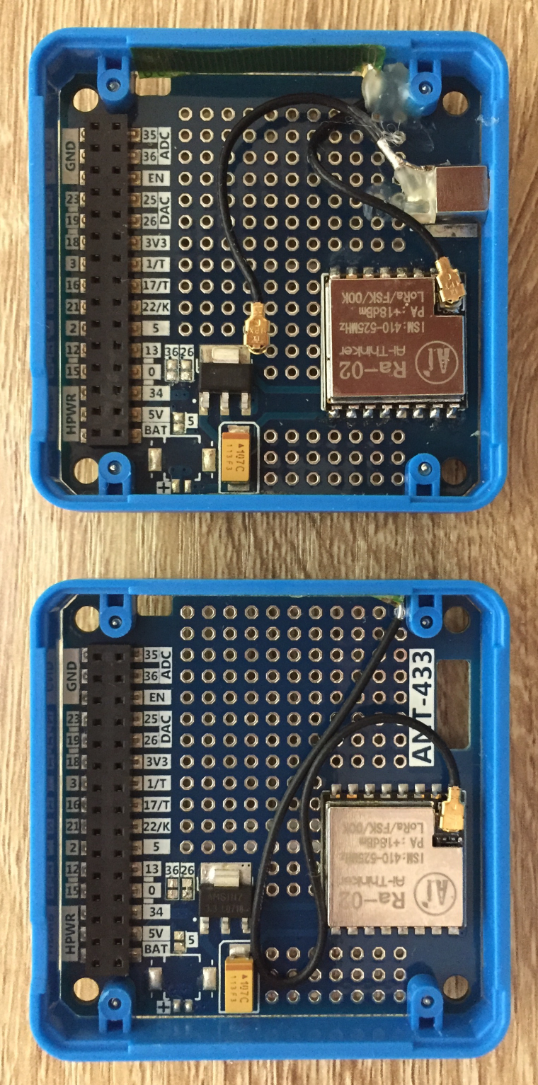
In the case of the LoRa module, I'm using all the default pins, so there's no need to solder any bridges or scrape any wires. I bought a LoRa board and only then realised that LoRa is more fun if you have two boards (I had two M5Stack main units already). So I bought another one and got a slightly different unit. The picture shows the unit I first got on the bottom, and the second one on top. As you can see the new unit has a connector for an external antenna as well as an internal one. In the picture you see the pigtail for the internal antenna connected, it came with the external antenna jack connected. After taking this picture I taped down the other pigtail with a little square of duck tape so it doesn't touch anything important.
The M5Stack LoRa uses the RA-02 radio module by AI-Thinker (datasheet) that is itself built around the Semtech SX-1278 transceiver chip (datasheet). If you actually start playing with the LoRa module, you might also want to read this article that GoJimmyPi wrote on it.
Also note for your information that the following information is in the M5Stack documentation on the website as of Jun 20, 2018:

This seems to be correcting something that is wrong elsewhere but it is actually wrong itself: RST is GPIO 26 and INT is 36. I measured it on both my boards with a multimeter, RST is really pin 26 and it would have to be because on the ESP32, GPIO 36 is input only so it could never drive the RST pin.
People that want to save on available GPIO pins could leave off the reset pin. In that case, just pass -1 as the reset pin number, the second argument of LoRa.setPins in the M5LoRa library. If a pin is provided, all the library does is pull it low briefly once when you call LoRa.begin().
It doesn't seem to affect all units, but in order to prevent a problem where the screen stays white, pull up pin 5, the CS pin of the LoRa, before initialising the m5 library. This is done as follows:
pinMode(5,OUTPUT);
digitalWrite(5,HIGH);
m5.begin():
GSM (SIM800L)
TXD	16	(16)
RXD	17	(17)
RST	 2 (!)	(5)
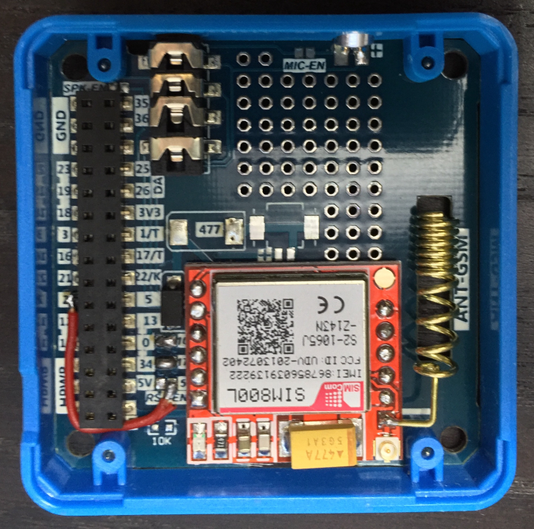
Rx and Tx can use the default pins for UART2, but as you can see in the LoRa section above, we have already used the pin used to reset the GSM (GPIO5) as the LoRa ChipSelect pin, so we have to choose something else here. Unfortunately the solder jumpers do not allow for any other choice, so I carefully scratched out the hidden trace between the two pads of the 5 solder bridge and soldered in a little wire from the GSM side of that bridge across to a free pin, choosing GPIO2. Note that you want to unscrew the boards from the plastic frames with a little hex screwdriver before soldering wires in.
The M5Stack SIM800L GSM board has a SIMCom "Core Board" module on it (the board with the red solder mask) that itself sports a SIM holder and a SIMCom SIM800L module (datasheet). This is a quad band GSM with GPRS, but no EDGE, 3G, LTE or anything else fancy.
People that want to save on available GPIO pins could again leave off the reset pin: unless your code pulls it low it is not used.
GPS
TXD	13	(16, 3, 13)
RXD	15 (!)	(17, 1, 5)
PPS	34	(34, 35, 36)
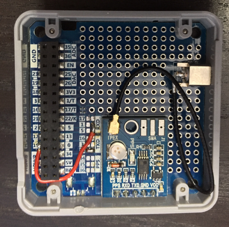
The PPS signal provides one pulse per second, not very interesting unless you want to do very precise timing. I've already used the 17/16 default for the GSM above. So that means I started by carefully scraping away the traces between the solder bridges marked 16 and 17, checking with a multimeter that the connections are really gone. (Note that if you don't scrape away the traces inside the solder bridges, you will connect UART2 and UART1, leading to all sorts of surprisingly hard to debug grief.)
I put the Tx at 13, which is a simple solder bridge, but the only solder bridge choices for Rx are 17 (UART2 default, in use by the GSM above), 1 (in use by the USB serial that talks to your computer) and 5 which is the default ChipSelect pin for the LoRa. So I put in a wire again, this time to GPIO15.
The GPS module used is a u-blox NEO-M8 (datasheet).
People that want to save on available GPIO pins could again leave off the reset pin, as well as the RX pin of the GPS module. After all: if you are happy with the NMEA data that the module provides by default, you don't need to talk to it. And you can also very safely leave off the PPS pin, if your code is not using this one pulse per second signal.
Testing it all
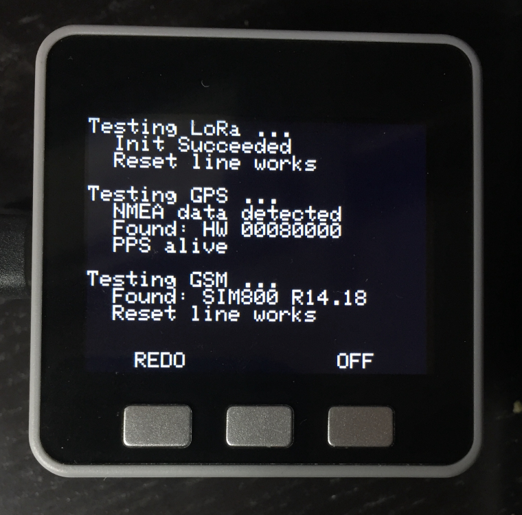
Now comes the time to test if all connections to each of the modules work. I have written BoardTest.ino, which should show you (in actually readable type) if your hardware is detected. You can set any pins you haven't hooked up to -1, the test program will then skip all the non-applicable tests.
#include <M5Stack.h>
#include <M5LoRa.h>

HardwareSerial GPS(1);
HardwareSerial GSM(2);

// Change these if your boards are wired differently
//
// Any pins not hooked up can be set to -1 to skip tests
//
const int LORA_CS  =  5;
const int LORA_RES = 26;
const int LORA_INT = 36;
const int GPS_RX   = 15;
const int GPS_TX   = 13;
const int GPS_PPS  = 34;
const int GSM_RX   = 17;
const int GSM_TX   = 16;
const int GSM_RES  =  2;

// The bytes to be sent to the GPS to request the version info packet back.
const uint8_t UBX_MON_VER[] PROGMEM = { 0xb5, 0x62, 0x0a, 0x04, 0x00, 0x00, 0x0e, 0x34 };


void setup() {

  String response;
  unsigned long started, last_ati, last_time, time_before_last;
  char resp_buf[50];
  unsigned int i, pps_state;

  if (LORA_CS != -1) {
    pinMode(LORA_CS, OUTPUT);
    digitalWrite(LORA_CS, HIGH);
  }
  m5.begin():

  M5.Lcd.setTextSize(2);

  // Test LoRa
  ConsoleOutput ("Testing LoRa ...");
  if (LORA_CS != -1 && LORA_INT != -1) {
	LoRa.setPins(LORA_CS, LORA_RES, LORA_INT);
	if (LoRa.begin(433E6)) {
	  ConsoleOutput("  Init Succeeded");
	  if (LORA_RES != -1) {
		LoRa.setPins(LORA_CS, -1, LORA_INT);
		pinMode(LORA_RES, OUTPUT);
		digitalWrite(LORA_RES, LOW);
		if (LoRa.begin(433E6)) {
		  ConsoleOutput("  Reset line does not work");
		} else {
		  ConsoleOutput("  Reset line works");
		}
		digitalWrite(LORA_RES, HIGH);
	  } else {
		ConsoleOutput ("  Skipping reset test");
	  }
	} else {
	  ConsoleOutput("  Hardware Not Found");
	}
  } else {
	ConsoleOutput("  Skipping test");
  }

  ConsoleOutput("");

  // Test GPS
  ConsoleOutput ("Testing GPS ...");
  if (GPS_TX != -1 ) {
	GPS.begin(9600, SERIAL_8N1, GPS_TX, GPS_RX);
	GPS.setTimeout(1000);
	started = millis();
	while (true) {
	  response = GPS.readStringUntil(13);
	  response.replace("\n", "");
	  if (response.substring(0,2) == "$G") {
		ConsoleOutput("  NMEA data detected");
		if (GPS_RX != -1) {
		  GPS.setTimeout(500);
		  GPS.flush();
		  GPS.write(UBX_MON_VER, sizeof(UBX_MON_VER));
		  GPS.readStringUntil(0xb5);
		  GPS.readBytes(resp_buf, 50);
		  if (resp_buf[0] == 'b') {
			response = "";
			for (i = 35; i < 44 ; i++) response = response + resp_buf[i];
			ConsoleOutput("  Found: HW " + String(response));
		  } else {
			ConsoleOutput("  No response. RX ok?");
		  }
		} else {
		  ConsoleOutput("  Skipping bidir test");
		}
		break;
	  }
	  if (millis() - started > 2000) {
		ConsoleOutput("  No NMEA data found");
		break;
	  }
	}
	GPS.end();
  } else {
	ConsoleOutput("  Skipping serial tests");
  }

  if (GPS_PPS != -1) {
	pinMode(GPS_PPS, INPUT);
	pps_state = digitalRead(GPS_PPS);
	started = millis();
	while (true) {
	  if (digitalRead(GPS_PPS) != pps_state) {
		if (millis() - time_before_last > 900 && millis() - time_before_last < 1100) {
		  ConsoleOutput("  PPS alive");
		  break;
		}
		pps_state = digitalRead(GPS_PPS);
		time_before_last = last_time;
		last_time = millis();
	  }
	  if (millis() - started > 3000) {
		ConsoleOutput("  PPS not detected");
		break;
	  }
	}
  } else {
	ConsoleOutput("  Skipping PPS test");
  }

  ConsoleOutput("");

  // GSM testing
  ConsoleOutput("Testing GSM ...");
  if (GSM_TX != -1 && GSM_RX != -1) {
	if (GSM_RES != -1) {
	  pinMode(GSM_RES, OUTPUT);
	  digitalWrite(GSM_RES, HIGH);
	}
	GSM.begin(9600, SERIAL_8N1, GSM_TX, GSM_RX);
	GSM.setTimeout(200);
	GSM.println("ATI");
	started = millis();
	last_ati = millis();
	while (true) {
	  // send "ATI" every second in case the modem just woke up
	  if (int(last_ati / 1000) < int(millis() / 1000)) {
		GSM.println("ATI");
		last_ati = millis();
	  }
	  response = GSM.readStringUntil(13);
	  response.replace("\n", "");
	  if (response.length() > 6) {
		ConsoleOutput("  Found: " + String(response));
		if (GSM_RES != -1) {
		  started = millis();
		  GSM.println("ATI");
		  digitalWrite(GSM_RES, LOW);
		  while (true) {
			response = GSM.readStringUntil(13);
			response.replace("\n", "");
			if (response.length() > 6) {
			  ConsoleOutput("  Reset line broken");
			  break;
			}
			if (millis() - started > 2000) {
			  ConsoleOutput("  Reset line works");
			  break;
			}
		  }
		  digitalWrite(GSM_RES, HIGH);
		} else {
		  ConsoleOutput("  Skipping reset test");
		}
		break;
	  }
	  if (millis() - started > 4000) {
		ConsoleOutput("  No response to ATI");
		break;
	  }
	}
	GSM.end();
  } else {
	ConsoleOutput("  Skipping tests");
  }

  M5.Lcd.setCursor(45,220);
  M5.Lcd.print("REDO");
  M5.Lcd.setCursor(235,220);
  M5.Lcd.print("OFF");


}

void loop() {

   M5.update();

  if (M5.BtnC.wasPressed()) {
	M5.setWakeupButton(BUTTON_C_PIN);
	M5.powerOFF();
  }

  if (M5.BtnA.wasPressed()) {
	M5.Lcd.clear();
	M5.Lcd.setCursor(0,0);
	setup();
  }


}

void ConsoleOutput(String message) {
  Serial.println(message);
  M5.Lcd.println(message);
}
Et voila:

-
I've decided to update the original post to make it clearer in some parts, add some more detailed information as well as links to the datasheets of the modules. For the time being I'll keep updating this so we have a single reference point for information about these modules. Please let me know if you can think of other important information about any of these modules and I'll add it.
Eventually there should probably be a more formal reference manual for this project.
-
Ii just recently ordered these stacks and i guess you save me a ton of work.
thanks for taking the efforts of sharing. -
I've updated the BoardTest.ino code, text and images to reflect that it now tests all the wires to and from each board separately. So for instance, it sends a query to the GPS to see if the RX line is also hooked up, tests the GPS PPS signal and sees if the reset lines to the LoRa and GSM modules actually work. The text also documents which lines can be safely left off if you are low on GPIO lines.
-
Just used your code to test with a LoRa module.
I just have the black M5 Stack and the LoRa module, but the screen goes white when I have the LoRa module attached? -
@kieran-osborne With just the M5Stack and the LoRa module?
Try pushing it on a little harder first.
Try to see if there are any obvious shorts involving the MISO, MOSI or SCK lines, because that would cause the screen to not work. (Can you verify that it's still running by maybe printing something to the serial port?)
If that doesn't work maybe try cutting the traces between the solder pads one by one to see if it's one of those wires that the M5Stack doesn't like. But I think your SPI bus is shorted.
Rop
-
Hi Rop,
I have tried pushing a little harder on it but didn't change anything.
On the serial port i'm getting:
"Testing LoRa ...
Init Succeeded
Reset line works" -
I have had issues with my M5 Stack keep popping up on windows with USB device not recognised, so wonder if somehow they are related, is a bit strange
-
Hi rop,
When I run your code the screen is completely white,
but If i press the A button (button far left), it looks like it refreshes the screen and then the text is displayed?, weirder and weirder haha -
I think i've found the issue,
I think when the LoRa.begin function is called it is locking up the SPI so that it then can't talk to it, but on the next time round the loop the screen's SPI.begin is being called again so is able to access it and draw to the screen -
I've updated the post and the demo code inside it to show the fix of pulling up the CS pin on the LoRa board before initialising the screen to prevent the screen from staying white.