Deep Machine Vision and Random Grasping with Robotic Arms
-
Introduction
Today, I would like to share with you my experience using the myCobot320 M5 and FS820-E1 depth camera for an unordered object grabbing demonstration. Why did I choose to use a depth camera and robotic arm for this case study?
The commonly used 2D camera can capture two-dimensional images with pixel values in the horizontal and vertical directions. These cameras are typically used to capture static scenes or moving objects, and cannot provide depth information. In machine vision applications, 2D cameras can be used for tasks such as image classification, object detection, and recognition.
In contrast, depth cameras can capture depth information, allowing for the acquisition of three-dimensional information about objects. These cameras use various techniques to measure object depth, such as structured light, time-of-flight, and stereo vision. In machine vision applications, 3D cameras can be used for tasks such as point cloud segmentation, object recognition, and 3D reconstruction.
The information captured by 2D cameras is inadequate for certain special cases, hence the use of depth cameras to obtain more information, such as the length, width, and height of objects.
Let us begin our topic for today.
FS820-E1
Environment building
Firstly, I need to set up the development environment for the FS820-E1 depth camera using RVS, which is the software used for developing this depth camera. By utilizing the visual operator in RVS, I can quickly construct the node for the grabbing function.
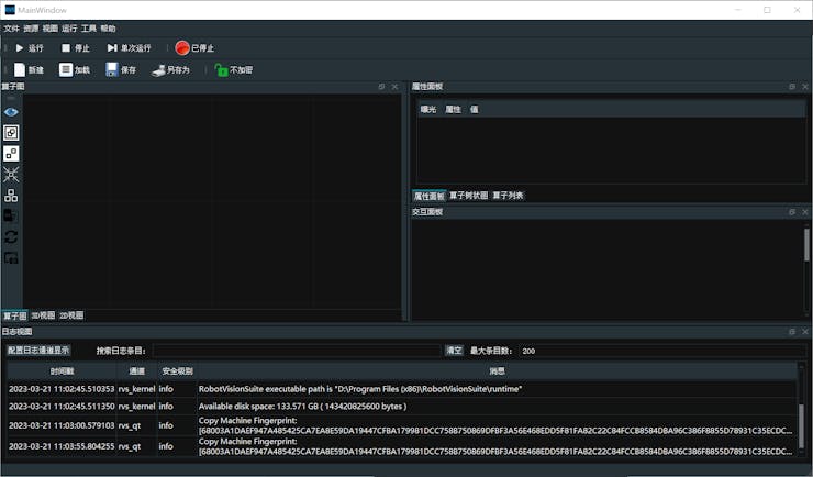
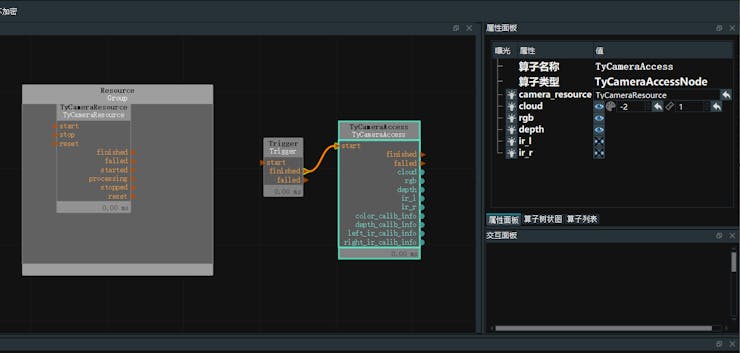
In the resource window located at the top left corner, locate the TyCameraResource operator and add it to the ResourceGroup in the operator graph. In the operator list, search for the TyCameraAccess and trigger operators, and add them to the operator graph. Adjust the operator parameters according to the requirements. Then, click on Run and set the Trigger->true in the property panel to visualize the data.TyCameraResource operator
● The start and stop operators are used to respectively initiate and terminate the thread of the resource operator. The auto_start option is also used to initiate the resource operator. If it is checked, the resource thread will only automatically start when entering the running state for the first time after opening the RVS software.
● The reset option is used to reset the attribute parameters if they need to be changed after opening the resource thread.
TyCameraAccess operator
● Open the visualization properties for cloud, RGB, and depth, and set the cloud_color to -2, which represents the true color.
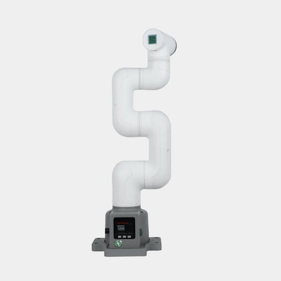
myCobot 320-M5Stack
The myCobot 320 is a practical robot designed for user-independent programming and development. The product has a maximum effective arm span of 350mm, a maximum load of 1KG, and a repetitive positioning accuracy of ±0.5mm. It supports development in various programming languages.
Environment building
For this project, Python is being used and a compiling environment for Python needs to be set up, as well as installing the Pymycobot library, which enables control of the robotic arm's movement.
pip install pymycobot --upgrade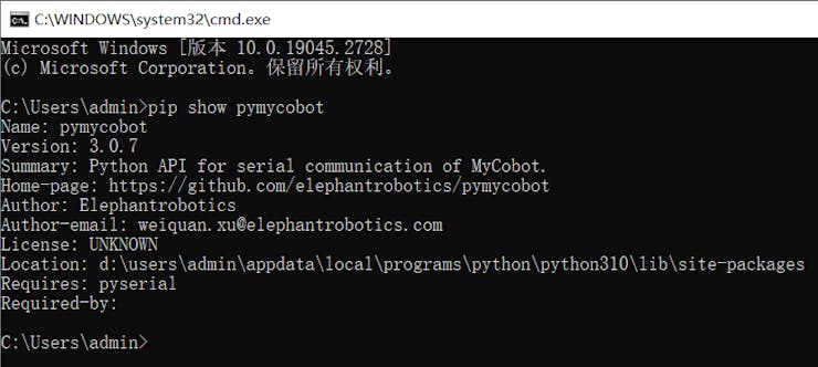
PS: It is recommended to use a computer graphics card that is at least a 1060 2G discrete graphics card for this project because it requires image recognition and other operations that can benefit from a higher-performing graphics card. The better the graphics card's performance, the faster the program will run. A 3060 graphics card is recommended.Random object grasping.
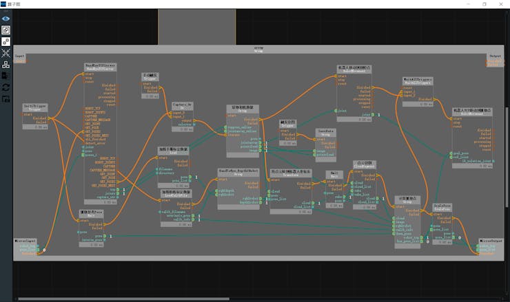
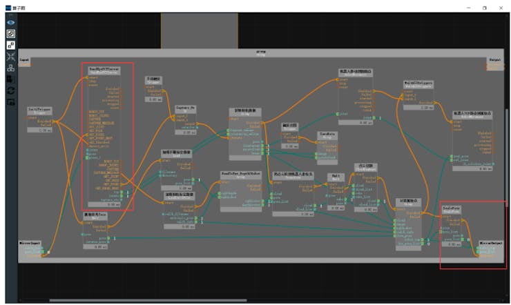
Next, we will implement the random object grasping of the robotic arm, which can accurately grasp the object in any posture. The following image shows the overall operator graph, which is the unstacking.xml.
Hand-eye calibration
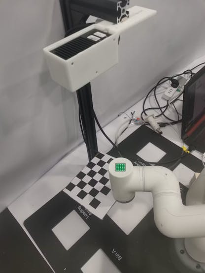
Using a chessboard pattern for hand-eye calibration.
Preparation:
● Prepare a chessboard, determine the number of rows and columns, and the length of each square (in mm).
● Hand-eye calibration can be divided into two types: eye in hand and eye to hand. Depending on the situation, fix the calibration board and the camera. Here we choose eye to hand calibration.
Data recording
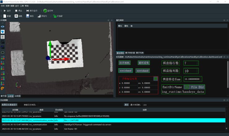
open unstacking_runtime/HandEyeCalibration/HandEyeCalibration.xml
Correctly fill in the number of rows and columns of the calibration board, the unit length of the calibration board cells, and the file path for saving the calibration data in the property panel.
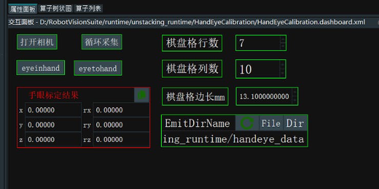
Before starting the calibration process, make sure that the camera can fully recognize the complete chessboard, and during the calibration process, the chessboard must be fixed and cannot be moved. After running the process, you will get 18 sets of data.
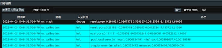
Calculation of indicator results
If the positional error is within 0.005 (5mm), then it is considered an ideal result.
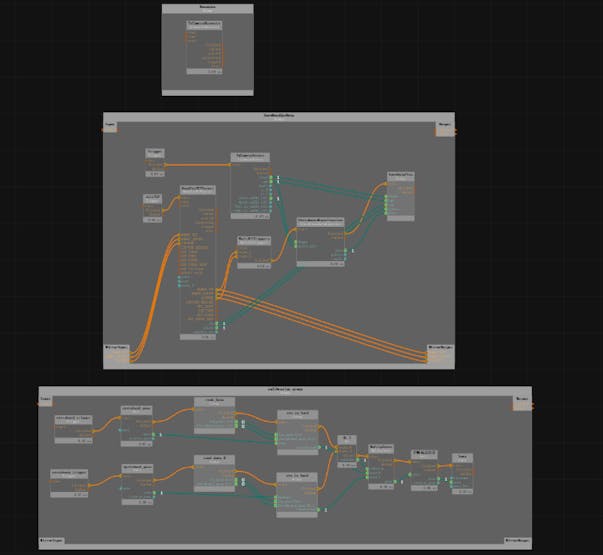
Coordinate system conversion
The following steps aim to transform the coordinate system of the point cloud from the camera RGB lens coordinate system to the robot coordinate system, which involves camera extrinsic parameters and hand-eye calibration results.
Steps:
-
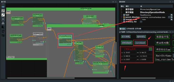
Right-click in the operator graph and select "Import Group XML here" to import the HandToEye_Depth2Robot.group.xml from the RVSCommonGroup. Besides this file, there is also HandInEye_Depth2Robot.group.xml.
-
Connect the pose port of the hand-eye calibration data group to the rgb2robot port of the HandToEye_Depth2Robot group.
-
Drag in the LoadCalibFile operator to load the calibration file, connect the finished port to the start port of the HandToEye_Depth2Robot group, connect the extrinsic_pose port to the rgb2depth port, and connect the start port to the InitTrigger port of the finished port. The specific connections are as follows:
-
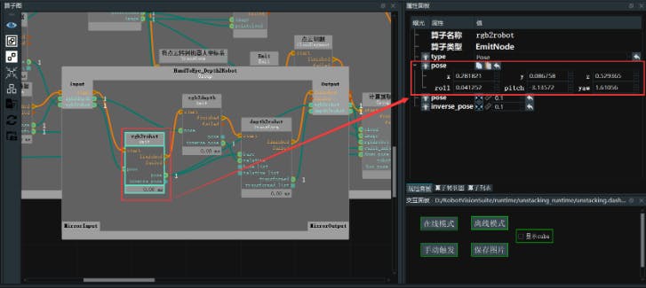
Click on the Group, find the rgb2tcp operator, and in the properties panel, paste the hand-eye calibration results in the "pose" property.
-
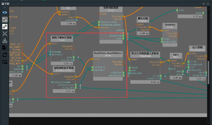
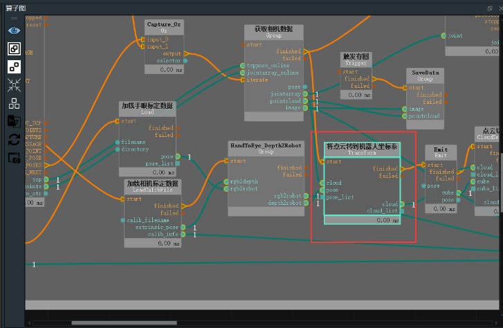
Through the previous steps, we have obtained the transformation matrices from the RGB camera to the robot coordinate system (rgb2robot) and from the depth camera to the robot coordinate system (depth2robot). Here, we will transform the point cloud from the depth camera coordinate system to the robot coordinate system.
-
First, drag the Transform operator into the graph and select "PointCloud" as the type. Connect the depth2robot port to the pose input port of this operator, and connect the pointcloud port of the LoadLocalData operator group to the same-named input port of this operator.
AI training
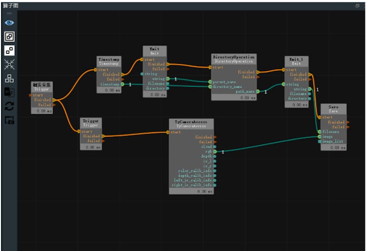
Acquire training images
To open the file unstacking_runtime/MaskRCNN/ty_ai_savedata.xml, you can use a text editor like Notepad or a code editor like Visual Studio Code. The contents of the file are similar to recording RGB images, and you just need to adjust the string parameter in EmitString to the desired file path. Once you have set the file path, you can click on Capture to record the images. It is recommended to record as many images as possible to ensure stability in the data.
Annotate the trained model
Currently, we have recorded the RGB annotations. We recommend using the labelme software for annotation, and this document provides a method for installing labelme.● 1. Install pip according to the official website:
https://pip.pypa.io/en/stable/installation/
● 2. Install PyQt5:
pip install PyQt5
● 3. Install labelme:pip install labelme
Preparation:First, determine the task goal and clarify which objects need to be detected during the detection process and which objects do not need to be detected, so as to carry out targeted annotation.
The annotation conditions given do not need to be overly strict. Do not think according to human thinking, but whether the annotation ideas set by yourself are easy to implement in the code.
Process:
● Open labelme in the terminal and click "OpenDir" to select the path where our annotations are located (the Emit operator string path in step 3.2.1 for collecting training images).
● Click "Create Polygons" to draw a red border around the wooden blocks.
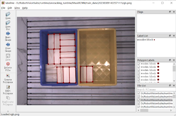
After finishing, a naming dialog will pop up. Please name it "wooden block" for the first time, and select it directly for subsequent boxes of the same type.● When all the boxes in the image have been labeled, click "Save" to save them with the default folder and name. Then select "Next Image" to switch to the next image.
Train AI model
Open the file unstacking_runtime/MaskRCNN/ty_ai_train.xml, and adjust the paths for data_directory and classnames_filepath. Then click on the "start_train" button to start the training process.After the training process is completed, a folder named "train_output" will be generated. In this folder, there will be a model file (ending in.pth) which contains the required weights for the trained model.
AI reasoning
-
Drag in an Emit operator, select "pose" for the type attribute, rename it to "Grasp Reference Pose", and input "3.141592654" for the pose_roll. This operator will be used in subsequent operators. Connect the pose port of this operator to the down_pose port of the Compute Grasping Point group.
-
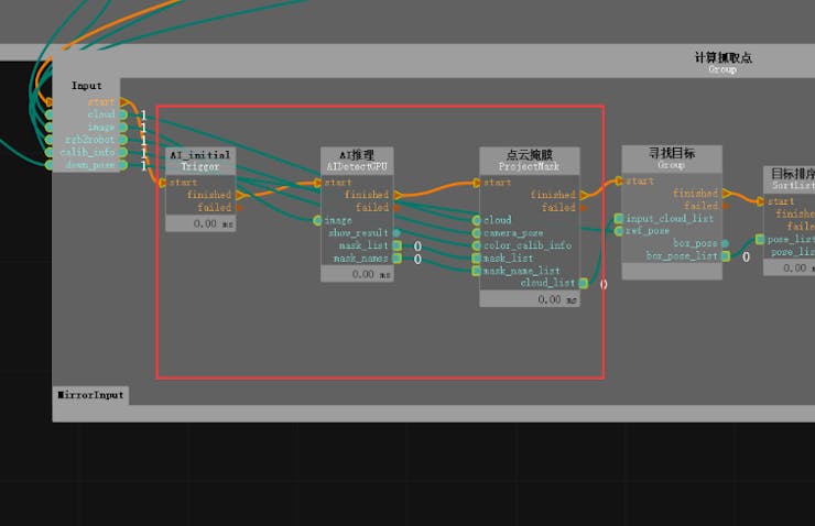
Double-click to expand the Compute Grasping Point group. The data needs to be pre-trained using the MaskRCNN network. Change the type of the AIDetectGPU operator to MaskRCNN and modify the rest of the configuration file parameters accordingly. Since the AI inference operator needs to be initialized before running, an extra Trigger (type is InitTrigger) needs to be added before the operator.
-
The AI inference operator will obtain the position region of the target in the 2D image (i.e., the mask image, corresponding to the obj_list port). Next, we need to convert these position regions to 3D point clouds, which is the ProjectMask operator in the Compute Grasping Point group. For the ProjectMask operator, we not only need to input the obj_list obtained by the AI inference operator, but also the 2D image corresponding point cloud, the transformation matrix between the 2D image camera coordinate system and the point cloud coordinate system, and the intrinsic parameters of the camera's RGB lens. Here, the point cloud has been converted to the robot coordinate system, so the transformation matrix from the RGB lens to the robot coordinate system needs to be input. The intrinsic parameters of the camera's RGB lens can be directly read from the camera parameter file. After the operator runs, a list of point clouds for all detected targets will be obtained.
Robotic arm positioning and grasping
location and Identification
According to the AI inference process, the point cloud list of all detected targets in the robot coordinate system has been obtained. Next, we need to obtain the centroid coordinates of its point cloud. -
Double-click to expand the Find Target group in the Calculate Grasp Point group. We need to first select the wooden block, and then sort the wooden blocks based on their Z-axis coordinates, selecting the topmost wooden block. Therefore, the FilterBoxList operator is used here and renamed to "PointCloud Height Sorting", with the following property values adjusted:
-
Obtain the plane using the FindElement operator, select "Plane" for the type, and obtain a plane suitable for grasping in the point cloud. Adjust the distance_threshold property value of the operator to adjust the selected plane. Open the cloud visualization property to view the selected plane.
-
Obtain the center point of the plane using the MinimumBoundingBox operator, rename it to "Get Bounding Box", select "ApproxMVBB" for the type attribute to obtain a convenient coordinate center point for the robot to grasp. Here, give the operator a ref_pose, which is connected to "TowardsDownPose" mentioned in 3.3.4 during AI inference, indicating a 180° rotation around the X-axis, so that the Z-axis faces downward for ease of robot grasping. Open the box and box_pose visualization properties in the "GetBoxCube" attribute panel to display the calculated center point of the plane.
-
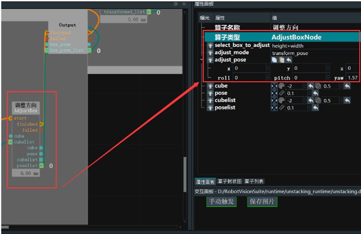
Adjust the direction of the wooden block using the AdjustBoxNode operator, which selects objects with a length greater than their width and changes the object pose. Here, select a yaw of 90°.
Grasp by the robotic arm
After completing the above operations, the target point coordinates have been obtained, and it is necessary to establish a TCP connection between the robot and the RVS software and carry out actual grasping. -
Write TCP communication code (RobotControl_Elephant.py). The following is a snippet of the code that implements TCP communication between RVS software and the robotic arm.
#CAPTURE print("***get pose***%s"%time.asctime()) capture_cmd = "GET_POSES \n" capture_bytes=bytes(capture_cmd,encoding="utf-8") sock_rvs.send(capture_bytes) #recv CAPTURE data = sock_rvs.recv(socket_buf_len) print("---------------------------get data----------------------------") print(data) print("***data end***%s"%data[-1:]) print("***capture_receive***%s"%time.asctime()) if int(data[-1:]) == 1: print("***received CAPTURE result***\n") if int(data[-1:]) == 2: print("***All finished!***") #P_FLAG = bool(1-P_FLAG) #print("change poision") continue #break-
Adjust the target point coordinates using the ScalePose operator. Set the type to "Normal" and adjust the scale_rpy property to convert the roll, pitch, and yaw values from radians to degrees.
-
Finally, connect the finished and pose_list ports of the ScalePose operator to the MirrorOutput port of the outermost operator group and connect it back to the HandEyeTCPServer operator. With this, the project file editing is complete.
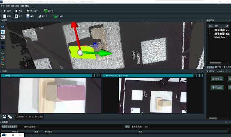
Show results
After completing the above steps, under the unstacking.xml project, click Run, and run the RobotControl_Elephant.py file at the same time. After identifying multiple blocks, select one of the block poses and send it to the robotic arm for gripping.
Summary
Overall, this is just a small part of what a depth camera can do. In the future, we may even consider stacking these objects together or using other irregular shapes to demonstrate its powerful performance. By training the model in advance, we can achieve the desired results. What do you expect me to do with it? Please leave a message below. Your likes and follows will be my motivation for updating more content!
-