UIFlow and CAT M MODULE SIM7080G
-
Hi,
I'm trying to use the CAT-M module with SIM7080G with https://flow.m5stack.com, setting the PSM mode and wake up the modem, sending an MQTT message via unsolicited request.
Reading this document there are only two Wake-up conditions:- T3412 timer is expired
- Pulling PWRKEY to low level
I want to use the PWRKEY way to wake up the modem, following this post I have to set the PIN to HIGH then to LOW (there is an inverted in the middle).
This is my UI FLow code
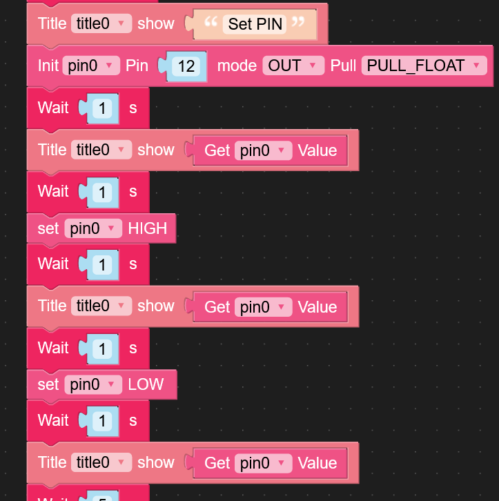
It works to change the PWRKEY status but if I try to send a new MQTT message after this code nothing happen and the message has not been delivered, so the modem seems to be in PSM mode yet.Can someone help me figure out where am I wrong?
Thanks in advance
Roberto -
Hello @Rob-Dor
my tests confirm that after waking up SIM7080 from PSM with the PWRKEY and without disabling PSM, the modem eventually drops back into PSM. So yes, in this case all further AT command are ignored.
So after waking the modem send
AT+CPSMS=0to disable PSM, send MQTT messages etc. and when you're done, enable PSM again.BTW: you should see the LED on the modem blinking slowly while not in PSM. And the LED should be off during PSM.
Thanks
Felix -
Hi @felmue,
thanks for your answer, could you please share the code you used? Because I cannot wake up the modem in any way so I think I'm wronging something or if you prefer I can share my code and you have a look at it
Regards,
Roberto -
@felmue
Thanks, this is teiafra, teammate of Rob.Dor. Please note that we're using this module https://docs.m5stack.com/en/base/iot_base_catm?ref=langship which does not show any kind of LED or light to our eyes -
Hello guys
@Rob-Dor : sure, I'll have a look. If possible, can you reduce your code to the minimum showing the issue? Thanks
@teiafra : you are correct, the
iot_base_catmmodule doesn't have an LED on the NETLIGHT output (which is a shame).However it does have a red LED for the STATUS output which can also be used as indicator.
- STATUS LED on : modem is powered and on
- STATUS LED off : modem is either off or in PSM mode
Can you confirm that the red STATUS LED is on when the modem is powered on and off when it is in PSM mode?
Note: I am using a modified
catmunit for my testing - theiot_base_catmmodule is ordered and it is on its way.Thanks
Felix -
@felmue
I confirm that iot_base_catm module contains a red led as you said: thanks!
Indeed this is reported in the schematic and the led is connected to the STATUS pin.
BUT it is not visible at all from outside and to see it you need to remove the Guide rail mount base plate and "spy" through the hole close to the antenna's connector: that's not confortable. See photo.
We'll let you know if it behaves with PSM toggle, as you suggested.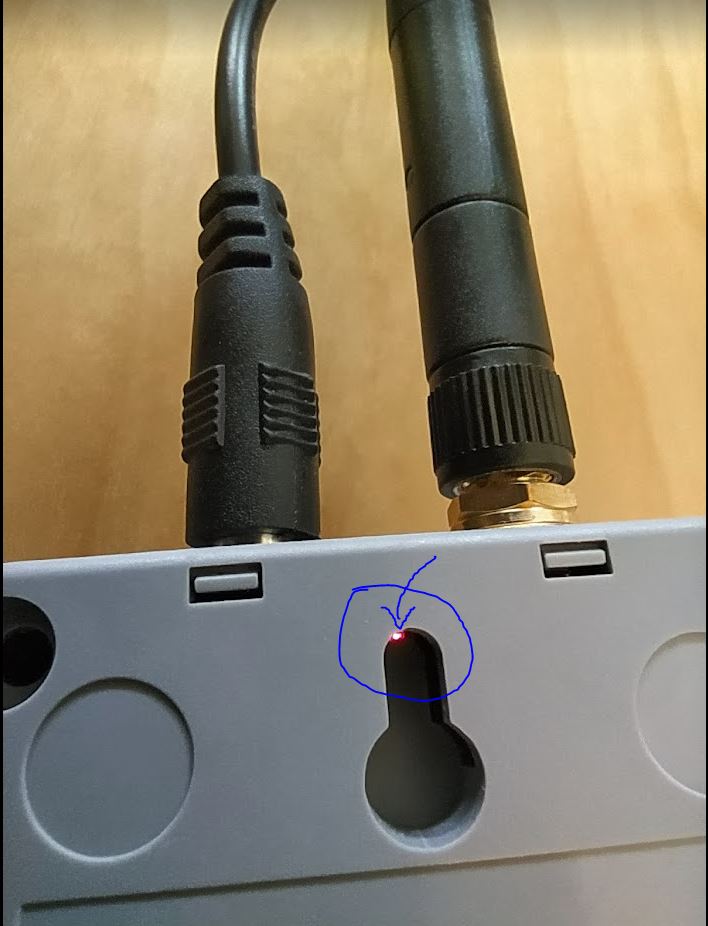
-
Hello @teiafra
thank you for sharing. I wasn't aware that the STATUS LED is practically hidden. I guess I'll have to modify my CatM IoT base when it arrives. I probably will also add the NETLIGHT LED which is very useful to know in which state the modem is.
Thanks
Felix -
Hello @felmue
we confirm that that STATUS led is- ON when module is active
- OFF when module is either off or during PSM sleeping time
Looking at that led when PIN 12 is toggled to get the module to wake up we noticed
- HIGH then LOW: the led switches from off to on firmly
- LOW then HIGH: the led switches on but then goes off or blinks very slowly
Could you confirm us which of the two sequences is the right order?
Simcom says that the PWRKEY should be pulled low then up again, but we understood there is an inverter in between PWRKEY and GPIO12, so the logic to apply is flipped. Thus we guess the "HIGH then LOW" was good and indeed the led stays on.
If you do the opposite pulses the module would reset and we supposed that the LED bliking means that.
However the last "check module status" instruction return always False, as if the module stays down even if the led light is on. In addtion wherever we put the CPSMS=0 (before or after the two pulses) it seems that the content in the UART is ignoredWe're now halted :-(
-
Hello @teiafra
from the schematic I understand that the PWRKEY logic is inverted, so in my opinion the correct sequence is HIGH then LOW. (And the status LED being firmly on seems to confirm that.)
In my experience the first AT command after the modem wakes up from PSM sleep is always ignored / lost. Try issuing the
Check module statuscommand multiple times.Thanks
Felix -
@felmue
we found a sequence which is almost working. See picture.
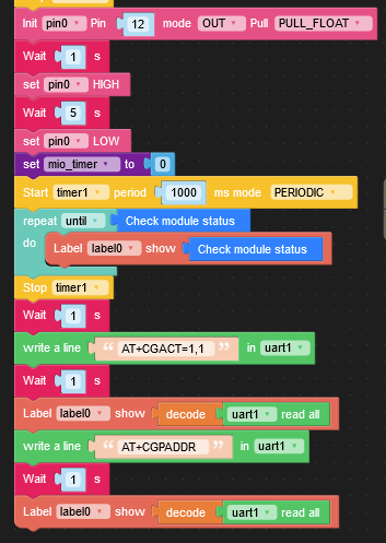
The right toggle is indeed from HiGH to LOW and should last not less than 1s nor longer than 12s ( the latter will force a reset). We used 5s.
According to the SIMCOM 7080G Hardware integration Guide the UART should be active after 1.8s from the first HIGH pulse.
Then the code checks iteratively the module status, which becomes True after 3 more seconds (according to the timer put in between and printed out).
At this stage we are pretty confident the UART is up & running and activate the connection and check IP address. Both UART reading are successful (connection setup and IP address returned).
NOTE: we saw that the very first AT command after wake up is caught with those timings above.FAILURES:
- there is not way to catch the unsolicited "EXIT PSM" message from the UART. We are able to catch +CPSMSTATUS: ENTER PSM (URC was enabled in advance with AT+CPSMSTATUS=1) at any try but never ever to get EXIT PSM (UART remains empty)
- In addition, although the module gained again IP connectivity any attempt to move MQTT or HTTP traffic fails (the MQTT client of the new IoT Base CAT-M palette crashes, while perfectly work with no PSM at all)
-
@felmue
I tried to implement a loop that scans the UART until there is some content and in this case decode it and print it out. See screenshot.
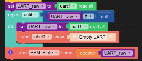
Well, I put it soon after the wake up pulse sequence to catch the URC EXIT PSM. Nothing: label0 stamps "Empty UART" all the time and instead the "PSM_State" label never assumes "EXIT PSM" string.
I'm going to give up -
-
Hi @felmue and many thanks: we'll have look.
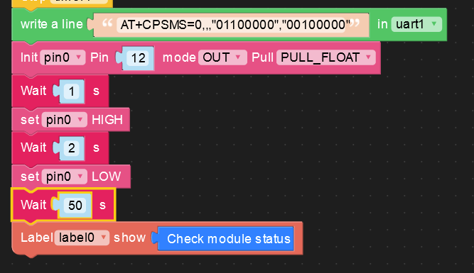
From our side, good news. M5Stack guys gave us the tip to set ECHO OFF once the module is resumed from the sleep, so soon after PWRKEY sequence, our code checks module status and then set echo off.

In this way we're able to launch the MQTT client (provided with the new IoT Base CAT-M palette) and publish a topic.We were not able to catch the "EXIT PSM" URC. We noted however that if the code invoked earlier the "network active" brick the URC shows +APP PDP DEACTIVE (we guess that TCP sockets are closed as well as any protocol layer above IP is terminated) while if the code never invoked "network active" before the PSM then we catch "ENTER PSM" URC.
At this stage our investigation around PSM is pretty satisfactory of the results achieved.
We'll keep you updated about any further progress.
Thanks!! -
Hello! It looks like you're interested in this conversation, but you don't have an account yet.
Getting fed up of having to scroll through the same posts each visit? When you register for an account, you'll always come back to exactly where you were before, and choose to be notified of new replies (either via email, or push notification). You'll also be able to save bookmarks and upvote posts to show your appreciation to other community members.
With your input, this post could be even better 💗
Register Login