GPS GPIO Question
-
I'm using an M5Stack GPS Module as part of an NTP project but for locational reasons (GPS Signal Issues!) I need to connect the pins on the module to to a through a TTL to RS232 adapter and into a USR-TCP232-302 Serial to Ethernet Converter and while I have it running fine on my USB powered TTL adapter I wanted to check I had the right GPIO pins selected.
- Is the GPIO Pin 28 Connecter 5V output? I would normally connect to the VIN for this but my board has 2 VIN connectors and I cant find anywhere online which one is positive?
- On the newer boards is GPIO Pin 34 still the PPS Output?
Stuart.
-
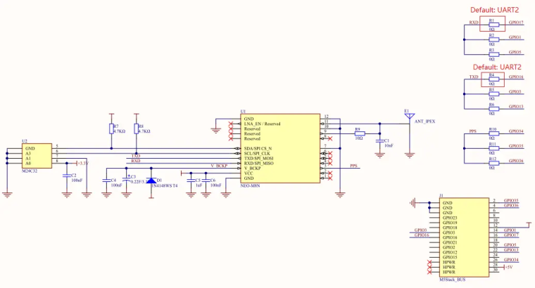
Hi, you could refer to the schematic.
-
The GPIO is connected to the PIN12.(3.3V).
-
The newer boards (COMX.GPS). don't have PPS output.
-
-
Are you sure that's the correct schematic for the current ComX.GPS as there are a few differences when I compare the board against the schematics and against the UBlox NEO8 pin assignments, which lead me to assume the PPS is actually connected.
I can see on the board that the Chip Connection 3 (PPS) connects into the R9 Resistor while its unconnected on your schematic. The R9 resistor is also 20 Ohm on the board and 10ohm on your schematic. and I am assuming by this that I could connect to the resistor to obtain a PPS signal.
There is also a second difference that I have seen on n the board the IPEX antenna is marked F1 (E1 on your schematic) and connected into the C7 capacitor which isn't in your schematic,
-
not. this schematic is for the GPS Unit. (COMX GPS Module doesn't release the schematic yet).
I paste it here just want to tell you the PIN28 of the M5BUS is 5V output. (if you are using the CORE1,you even could use this pin for input or output)just like I said. The newer boards (COMX.GPS Module). don't have PPS output.
Hello! It looks like you're interested in this conversation, but you don't have an account yet.
Getting fed up of having to scroll through the same posts each visit? When you register for an account, you'll always come back to exactly where you were before, and choose to be notified of new replies (either via email, or push notification). You'll also be able to save bookmarks and upvote posts to show your appreciation to other community members.
With your input, this post could be even better 💗
Register Login