What is SYS_INT? (I don't understand your schematics)
-
I have an M5Stack with the watch bottom and I want to add an MPU9250 to it to detect wrist movement.
(I also have an M5StickC which comes with an MPU6886 built in, but it's lacking other features I need...)To get maximum compatibility for existing libraries, I would like to wire my MPU9250 to my M5Stack the same way it's being done for the M5StickC with the MPU6886.
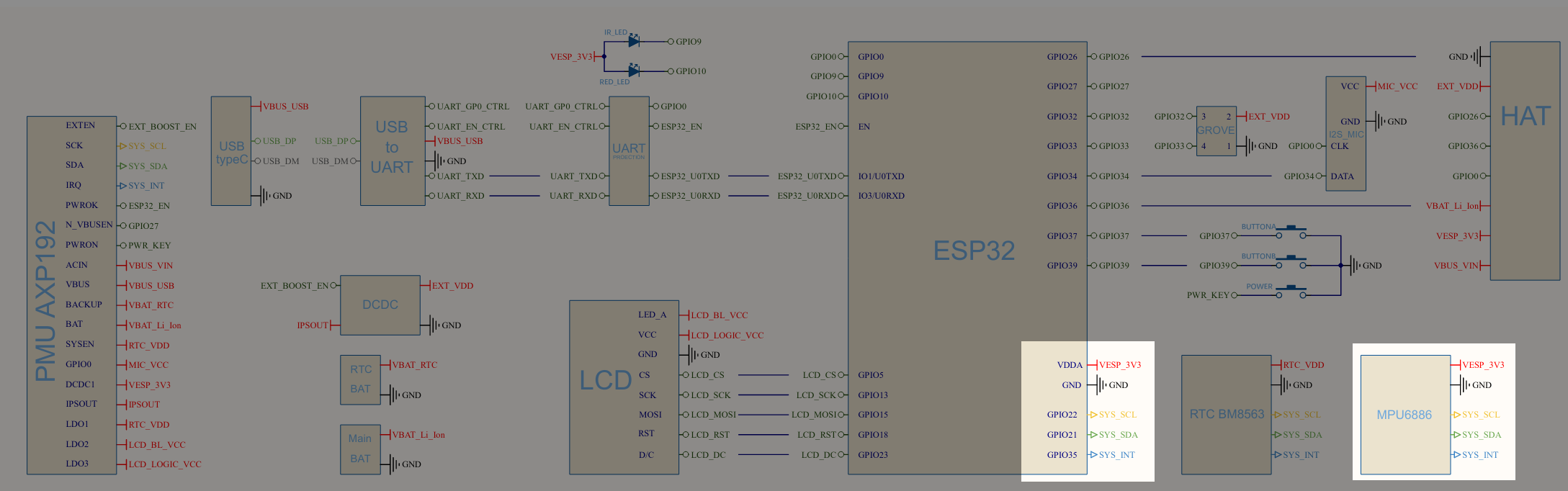
So I looked at the schematics:
I mean I can make a good guess about SYS_SCL, SYS_SDA, VESP_3V3 and GND.
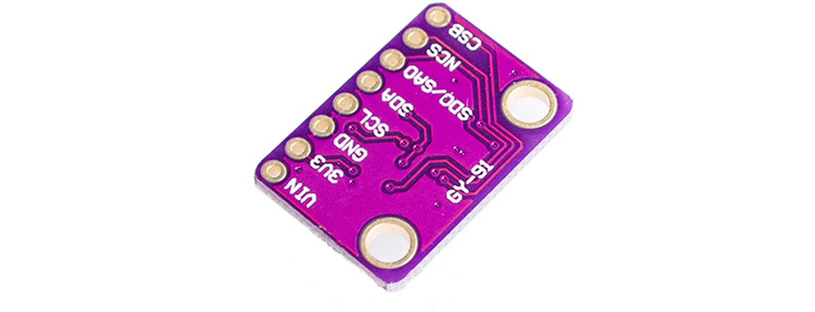
But what is SYS_INT? According to the schematics it's GPIO35 on the ESP32, but which pin is it on the MPU?My MPU9250 has the following pins: VIN, 3V3, GND, SCL, SDA, SDO/SAO, NCS, CSB:
So my guess so far is that i should connect it like this:
VIN -> not connected
3V3 -> 3V3
GND -> GND
SCL -> SCL (GPIO22)
SDA -> SDA (GPIO21)
SDO/SAO -> not connected
NCS -> not connected
CSB -> not connectedBut according to the schematics I'm missing a pin (SYS_INT).
Any help is appreciated.
-
this pin SYS_INT may be used to wake up a esp32 from deepsleep by interrupt signal on gpio35. if you don't need the processor wake up function after detecting movement / impact of the device then just don't connect this pin to your mpu. Treat it as a functionality that has probably not been used or documented by code so far (i mean this forum)
-
That's actually very interesting. I was planning to use the wrist movement detection to turn on/off the screen. But putting the ESP into deep sleep instead sounds like a fantastic idea.
But still, I know that SYS_INT is supposed to be GPIO35 on the ESP, but which pin of my MPU9250 am I supposed to connect to GPIO35?
VIN, 3V3, GND, SCL, SDA, SDO/SAO, NCS or CSB?
-
@somedude i think is that answer you could find in the datasheet of your mpu chip. In this document you find if your chip can use interrupts and how values settings in which registers to work. And also pinouts with description.
-
After taking a look at the specs of the specific board I have:
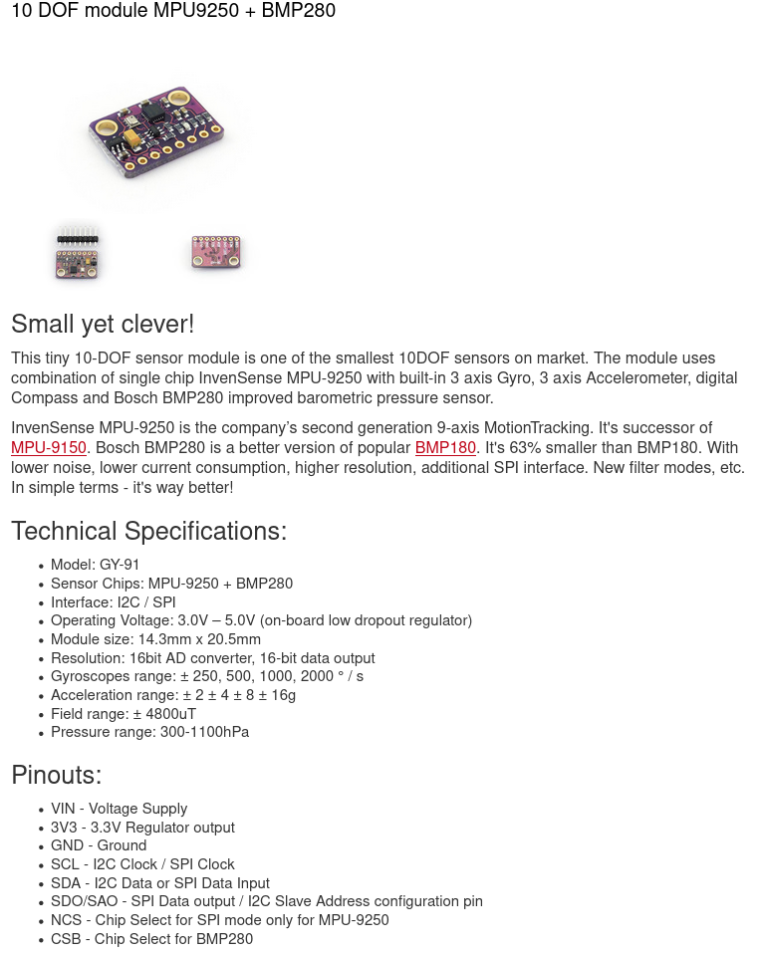
and at the specifications of the MPU9250 specifically:
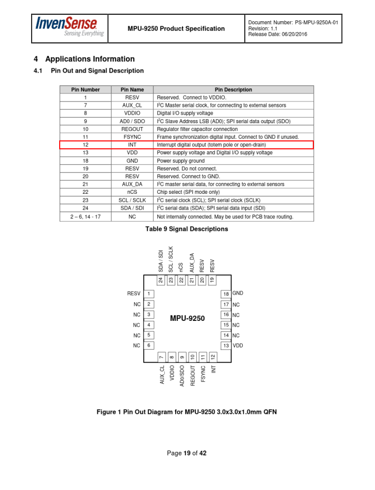
I came to the conclusion that it must be the INT pin of the MPU9250 and that pin cannot be accessed through the pinout of the PCB. I would have to solder a wire directly to it. And then maybe I'd also have to use a resistor, capacitor or whatever..
-
Hey, did you have any success and got it to work?
Would be awesome if you coulde provide an update.
greetings
Hello! It looks like you're interested in this conversation, but you don't have an account yet.
Getting fed up of having to scroll through the same posts each visit? When you register for an account, you'll always come back to exactly where you were before, and choose to be notified of new replies (either via email, or push notification). You'll also be able to save bookmarks and upvote posts to show your appreciation to other community members.
With your input, this post could be even better 💗
Register Login