KinoWheels M5Stack porting WIP...

-
Hi All, this is my porting of KinoWheels to m5stack using espnow to play wireless with R0nin
tested with:
R0nin 1TX: M5Stack + PROTO MODULE
RX: M5Atom Lite + GROVE cableSOFTWARE:
first we upload rx code to know the mac address on serial monitor
in the arduino IDE select M5StickC board for ATOM
#include "M5Atom.h"
#include <esp_now.h>
#include <WiFi.h>

#define WIFI_CHANNEL 1
uint8_t localCustomMac[] = {0x36, 0x33, 0x33, 0x33, 0x33, 0x33};
const byte maxDataFrameSize = 200;

// must match the controller struct
struct __attribute__((packed)) DataStruct {
  int X;
  int Y;
  int Z;
};
DataStruct myData;

#define BAUDRATE 100000  // oder  100000 115200
#define SERIALPORT Serial2  // - uncomment this line if using an arduino based board with more than one HW serial port


class BMC_SBUS
{
  public:
    uint8_t sbusData[25];
    int16_t servos[18];
    void begin(void);
    void Servo(uint8_t ch, int16_t position);
    void Send(void);
    void Update(void);

  private:
    uint8_t byte_in_sbus;
    uint8_t bit_in_sbus;
    uint8_t ch;
    uint8_t bit_in_servo;
};


void BMC_SBUS::begin()
{
  //intialise private data arrays
  //sbus_data is formatted for correct serial output
  //note that the actual 11bit sbus data for each channel is embedded across multiple data bytes in a very stange order
  //byte 1 and bytes 24 and 25 should be left as is
  //the first is a start byte, the last is a stop byte and the second last holds various flags
  //servos is the internal per channel position and is more straightforward - one int_16 per channel

  uint8_t loc_sbusData[25] = {0x0f, 0x01, 0x04, 0x20, 0x00, 0xff, 0x07, 0x40, 0x00, 0x02, 0x10, 0x80, 0x2c, 0x64, 0x21, 0x0b, 0x59, 0x08, 0x40, 0x00, 0x02, 0x10, 0x80, 0x00, 0x00};
  int16_t loc_servos[18]   = {1023, 1023, 1023, 1023, 1023, 1023, 1023, 1023, 1023, 1023, 1023, 1023, 1023, 1023, 1023, 1023, 0, 0};

  //setup serial port to transmit at 100k baud and use 1 parity and 2 stop bits
  //               (baud-rate/protocol/RXpin/TXpin/INVERT)
    SERIALPORT.begin(BAUDRATE, SERIAL_8E2, 32, 26, true); // ATOM GROVE PORT

  //setup public data arrays

  memcpy(sbusData, loc_sbusData, 25);
  memcpy(servos, loc_servos, 18);
}

void BMC_SBUS::Servo(uint8_t ch, int16_t position)
{
  //set servo position on single channel

  if ((ch > 0) && (ch <= 16))
  {
    constrain (position, 0, 2048); //keep within min/max values
    servos[ch - 1] = position; //expects a non zero starting index to the channel
  }
}

void BMC_SBUS::Send(void)
{
  //send data over serial port
  SERIALPORT.write(sbusData, 25); //according to docs for Serial we can send the array along as is without a loop
}

void BMC_SBUS::Update(void)
{
  //update positions for all servo channels within the SBUS data frame
  //ignores digital servos and any failsafe mode stuff that was originally written

  //clear out existing sbus data for all channel data bytes
  //ignores first and last bytes in the array (start and stop bytes)
  //mapping loop relies on initial 0 values - do not omit this step!

  uint8_t i;
  for (i = 1; i < 24; i++)
  {
    sbusData[i] = 0;
  }

  //reset counters

  ch = 0;
  bit_in_servo = 0;
  byte_in_sbus = 1;
  bit_in_sbus = 0;

  //format sbus data - maps sevo data array to sbus data array 1bit at a time
  //correctly deals with the little endian byte order in the process

  for (i = 0; i < 176; i++) //16channels*11bits = 176bits
  {
    if (servos[ch] & (1 << bit_in_servo)) //bitwise AND to check if the correct servo databit is set to 1
    {
      sbusData[byte_in_sbus] |= (1 << bit_in_sbus); //bitwise OR sets the correct sbus databit if true
    }

    //increment bit counters

    bit_in_sbus++;
    bit_in_servo++;

    //if end of sbus byte reset sbus bit counter and increment sbus byte counter

    if (bit_in_sbus == 8)
    {
      bit_in_sbus = 0;
      byte_in_sbus++;
    }

    // if we have reached bit 11 in the servo data increment channel index and reset servo bit counter

    if (bit_in_servo == 11)
    {
      bit_in_servo = 0;
      ch++;
    }
  }
}

//Declare BMC_SBUS Object
BMC_SBUS mySBUS;

// Sbus delay value
const int sbusWAIT = 7;      //frame timing delay in msecs

// Declare sbus control channels
int panChannel = 1;
int tiltChannel = 2;
int rollChannel = 4;


int sentX;
int sentY;
int sentZ;


/* ********************************************************
  /*                      Void setup                           *
  /* ****************************************************** */
void setup() {

  //  M5.begin();
  M5.begin(true, false, true);
  Serial.begin(115200);
  delay(200);
  Serial.print("\r\n\r\n");
  WiFi.mode(WIFI_AP);
  Serial.println( WiFi.softAPmacAddress() );
  WiFi.disconnect();
  if (esp_now_init() == ESP_OK)
  {
    Serial.println("ESPNow Init Success!");
  }
  else
  {
    Serial.println("ESPNow Init Failed....");
  }
  esp_now_register_recv_cb(OnDataRecv);

  sentX = 1023;
  sentY = 1023;
  sentZ = 1023;

  // Start BMC_SBUS object
  mySBUS.begin();

}

/* ********************************************************
  /*                      Void Loop                           *
  /* ****************************************************** */
void loop() {

  sentX = (myData.X);
  sentY = (myData.Y);
  sentZ = (myData.Z);

//  Serial.print("sentX ");
//  Serial.println(sentX);
//  Serial.print("sentY ");
//  Serial.println(sentY);
//  Serial.print("sentZ ");
//  Serial.println(sentZ);

  for (int i = 0; i < 1; i++) {   //SBUS needs data every 7 Milliseconds. I repeat it three times for some time to pass for calculating speeds.

    mySBUS.Servo(panChannel, sentX);
    mySBUS.Servo(tiltChannel, sentY);
    mySBUS.Servo(rollChannel, sentZ);

    // Update SBUS object and send data
    mySBUS.Update();
    mySBUS.Send();

    delay(sbusWAIT);

  }

  if (M5.Btn.wasPressed())
  {}

  M5.update();
}


void OnDataRecv(const uint8_t *mac_addr, const uint8_t *incomingData, int data_len)
{
  memcpy(&myData, incomingData, sizeof(myData));
  Serial.print ("MAC ADDRES = ");
  for (byte n = 0; n < 6; n++) {
    Serial.print (mac_addr[n], HEX);
  }
  stato ++;
  Serial.println ();
}
open arduino serial monitor and pick the receiver MAC ADDRESS.
put the receiver MAC ADDRESS, in the TX code instead of "XX"
#include <M5Stack.h>

#include <ESP32Encoder.h>

ESP32Encoder encoderX;
ESP32Encoder encoderY;

////////////////////ESPNOW/////////////////////////
#include <esp_now.h>
#include <WiFi.h>

#define WIFI_CHANNEL 1

esp_now_peer_info_t slave;

// RX MAC ADDRESS HERE
uint8_t remoteMac[] = {0xXX, 0xXX, 0xXX, 0xXX, 0xXX, 0xXX};

const uint8_t maxDataFrameSize = 200;

// must match the controller struct
struct __attribute__((packed)) DataStruct {

  int X;
  int Y;
  int Z;

};
DataStruct myData;
const esp_now_peer_info_t *peer = &slave;
uint8_t dataToSend[maxDataFrameSize];

unsigned long lastSentMillis;
unsigned long sendIntervalMillis = 10;
unsigned long sentMicros;
unsigned long ackMicros;

///////////////////////////FINE ESPNOW///////////////

int xStampEnd = 0, yStampEnd = 0, timeStampEnd = 0;
int xPassed, yPassed, timePassed;
int X = 1023, Y = 1023, Z = 1023;
int pulsesX, pulsesY;
int  potiX = 100,  potiY = 100;

byte gearX = 2;
byte gearY = 2;

bool toggleZ;
bool toggleUSD;

//bool StatoRX;


void setup() {
  M5.begin();
  Serial.begin(115200);

  M5.Lcd.clear(BLACK);

  M5.Lcd.fillRoundRect(5, 10, 310, 150, 10, TFT_BLACK);
  M5.Lcd.fillRoundRect(15, 20, 290, 130, 5, TFT_YELLOW);
  M5.Lcd.fillRoundRect(25, 30, 270, 110, 55, TFT_BLACK);

  M5.Lcd.fillRoundRect(5, 150, 310, 90, 10, TFT_BLACK);
  M5.Lcd.fillRoundRect(15, 160, 290, 70, 5, TFT_YELLOW);
  M5.Lcd.fillRoundRect(25, 170, 270, 50, 25, TFT_BLACK);

  M5.Lcd.setTextColor(RED);
  M5.Lcd.setTextSize(5);
  M5.Lcd.setCursor(80, 60);
  M5.Lcd.println("RONIN");
  M5.Lcd.setTextColor(YELLOW);
  M5.Lcd.setCursor(55, 180);
  M5.Lcd.println("P");
  M5.Lcd.setCursor(245, 180);
  M5.Lcd.println("T");

  M5.update();

  Serial.print("\r\n\r\n");
  WiFi.mode(WIFI_STA);
  Serial.println( WiFi.softAPmacAddress() );
  WiFi.disconnect();
  if (esp_now_init() == ESP_OK)
  {
    Serial.println("ESP NOW INIT!");
  }
  else
  {
    Serial.println("ESP NOW INIT FAILED....");
  }
  memcpy( &slave.peer_addr, &remoteMac, 6 );
  slave.channel = WIFI_CHANNEL;
  slave.encrypt = 0;
  if ( esp_now_add_peer(peer) == ESP_OK)
  {
    Serial.println("Added Peer!");
    Serial.println();
  }
  esp_now_register_send_cb(OnDataSent);

  ///////////////////////////////////////////////////////////////////////////////

  // clear the encoder's raw count and set the tracked count to zero
  encoderX.clearCount();
  encoderY.clearCount();

  // Attache pins for use as encoder pins
  encoderX.attachHalfQuad(2, 3);
  encoderY.attachHalfQuad(34, 35);

  //////////////////////////////////////////////////////////
  Serial.println("<ready>");
}

void loop() {
  M5.update();
  ariloop();
  M5.update();
  sendData();
  Serial.print("x");
  Serial.print(pulsesX);
  Serial.print("y");
  Serial.print(pulsesY);
  Serial.println("end");
  delay(20); // PROVARE A TOGLIERLA
}

void ariloop() {
  pulsesX = encoderX.getCount();
  pulsesY = encoderY.getCount();

  timePassed = millis() - timeStampEnd;
  xPassed = xStampEnd - pulsesX;
  yPassed = pulsesY - yStampEnd;

  if (M5.BtnC.wasReleased()) {
    gearY ++;
    if (gearY == 4) {
      gearY = 1;
    }
    M5.Lcd.fillRoundRect(25, 170, 270, 50, 25, TFT_BLACK);
    if (toggleUSD) {
      M5.Lcd.setCursor(140, 180);
      M5.Lcd.println("UP");
    }
    M5.Lcd.setCursor(55, 180);
    M5.Lcd.println("P");
    M5.Lcd.setCursor(105, 180);
    M5.Lcd.println(gearX);
    M5.Lcd.setCursor(205, 180);
    M5.Lcd.println("T");
    M5.Lcd.setCursor(255, 180);
    M5.Lcd.println(gearY);
    delay(200);
  } else if (M5.BtnB.wasReleased()) {
    toggleZ = !toggleZ;
    if (toggleZ) {
      M5.Lcd.fillRoundRect(25, 170, 270, 50, 25, TFT_BLACK);
      M5.Lcd.setCursor(55, 180);
      M5.Lcd.println("(");
      M5.Lcd.setCursor(120, 180);
      M5.Lcd.println("ROLL");
      M5.Lcd.setCursor(255, 180);
      M5.Lcd.println(")");
    } else {
      M5.Lcd.fillRoundRect(25, 170, 270, 50, 25, TFT_BLACK);
      if (toggleUSD) {
        M5.Lcd.setCursor(140, 180);
        M5.Lcd.println("UP");
      }
      M5.Lcd.setCursor(55, 180);
      M5.Lcd.println("P");
      M5.Lcd.setCursor(105, 180);
      M5.Lcd.println(gearX);
      M5.Lcd.setCursor(205, 180);
      M5.Lcd.println("T");
      M5.Lcd.setCursor(255, 180);
      M5.Lcd.println(gearY);
      delay(200);
    }
    delay(200);

  } else if (M5.BtnA.wasReleased()) {
    gearX ++;
    if (gearX == 4) {
      gearX = 1;
    }
    M5.Lcd.fillRoundRect(25, 170, 270, 50, 25, TFT_BLACK);
    if (toggleUSD) {
      M5.Lcd.setCursor(140, 180);
      M5.Lcd.println("UP");
    }
    M5.Lcd.setCursor(55, 180);
    M5.Lcd.println("P");
    M5.Lcd.setCursor(105, 180);
    M5.Lcd.println(gearX);
    M5.Lcd.setCursor(205, 180);
    M5.Lcd.println("T");
    M5.Lcd.setCursor(255, 180);
    M5.Lcd.println(gearY);
    delay(200);

  } else if (M5.BtnB.wasReleasefor(700)) {
    toggleUSD = !toggleUSD;
    if (toggleUSD) {
      M5.Lcd.fillRoundRect(25, 170, 270, 50, 25, TFT_BLACK);
      M5.Lcd.setCursor(140, 180);
      M5.Lcd.println("UP");
      M5.Lcd.setCursor(55, 180);
      M5.Lcd.println("P");
      M5.Lcd.setCursor(105, 180);
      M5.Lcd.println(gearX);
      M5.Lcd.setCursor(205, 180);
      M5.Lcd.println("T");
      M5.Lcd.setCursor(255, 180);
      M5.Lcd.println(gearY);
      delay(200);
    } else {
      M5.Lcd.fillRoundRect(25, 170, 270, 50, 25, TFT_BLACK);
      M5.Lcd.setCursor(55, 180);
      M5.Lcd.println("P");
      M5.Lcd.setCursor(105, 180);
      M5.Lcd.println(gearX);
      M5.Lcd.setCursor(205, 180);
      M5.Lcd.println("T");
      M5.Lcd.setCursor(255, 180);
      M5.Lcd.println(gearY);
      delay(200);
    }

  }

  if (M5.BtnA.isPressed() && toggleZ) {
    Z = 723;   //823, 1023, 1223
    delay(100);

  }   else if (M5.BtnC.isPressed() && toggleZ) {
    Z = 1323;//823, 1023, 1223
    delay(100);

  } else {
    Z = 1023;  //823, 1023, 1223
  }

  if (gearX == 1) {
    potiX = 100;
  }
  if (gearX == 2) {
    potiX = 200;
  }
  if (gearX == 3) {
    potiX = 300;
  }

  if (gearY == 1) {
    potiY = 100;
  }
  if (gearY == 2) {
    potiY = 200;
  }
  if (gearY == 3) {
    potiY = 300;
  }

  if (toggleUSD) {
    // GRAFICA UPSIDEDOWN
    potiX = potiX * - 1;
    potiY = potiY * - 1;
  } else {
    // GRAFICA DRITTA
  }

  X = 1023 + potiX * xPassed / timePassed;
  Y = 1023 + potiY * yPassed / timePassed;

  pulsesX = encoderX.getCount();
  pulsesY = encoderY.getCount();

  xStampEnd = pulsesX;
  yStampEnd = pulsesY;
  timeStampEnd = millis();

}

void sendData() {
  if (millis() - lastSentMillis >= sendIntervalMillis) {
    lastSentMillis += sendIntervalMillis;

    myData.X = X;
    myData.Y = Y;
    myData.Z = Z;

    uint8_t bs[sizeof(myData)];
    memcpy(bs, &myData, sizeof(myData));
    sentMicros = micros();
    esp_now_send(NULL, bs, sizeof(myData)); // NULL means send to all peers
    Serial.println("  sent data");
    Serial.println();
  }
}

void OnDataSent(const uint8_t *mac_addr, esp_now_send_status_t status)
{
  if (status == ESP_NOW_SEND_SUCCESS) {
    Serial.println("RX ACCESO");
    M5.Lcd.fillCircle(60, 60, 10, TFT_GREEN);
    //    StatoRX = 1;
  } else {
    Serial.println("RX SPENTO");
    M5.Lcd.fillCircle(60, 60, 10, TFT_RED);
    //    StatoRX = 0;
  }
  Serial.println();
}
HARDWARE
encoders wiring on M5Stack is a bit different of original kinowheels (arduino mega) one.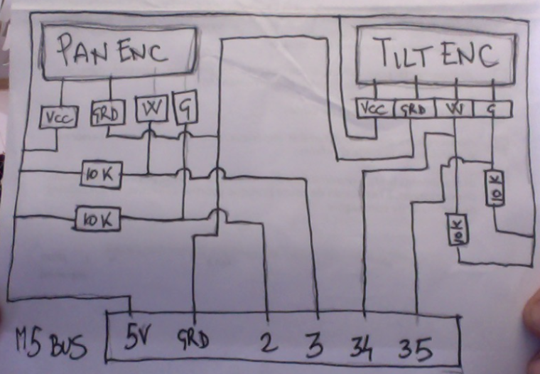
with esp32 based board you can invert ttl signal in serial.begin declaration... so no need to add a serial inverter IC for D-Bus, so ATOM GROVE cable go straight to R0nin D-Bus
GROVE ------ D-BUS
GRD ---------- Black
5V ------------ Red
TX ------------ White
RX ------------- Yellow (not connected on R0nin1) to test on R0nin2this is the code to use M5Stack kinowheels in the simulator:
#include <M5Stack.h>
#include <ESP32Encoder.h>

ESP32Encoder encoderX;
ESP32Encoder encoderY;

float pulsesX, pulsesY;

void setup() {
  M5.begin();

  M5.Lcd.clear(BLACK);

  M5.Lcd.fillRoundRect(5, 10, 310, 150, 10, TFT_BLACK);
  M5.Lcd.fillRoundRect(15, 20, 290, 130, 5, TFT_YELLOW);
  M5.Lcd.fillRoundRect(25, 30, 270, 110, 55, TFT_BLACK);

  M5.Lcd.fillRoundRect(5, 150, 310, 90, 10, TFT_BLACK);
  M5.Lcd.fillRoundRect(15, 160, 290, 70, 5, TFT_YELLOW);
  M5.Lcd.fillRoundRect(25, 170, 270, 50, 25, TFT_BLACK);

  M5.Lcd.setTextColor(RED);
  M5.Lcd.setTextSize(5);
  M5.Lcd.setCursor(130, 40);
  M5.Lcd.println("PC");
  M5.Lcd.setTextColor(YELLOW);
  M5.Lcd.setCursor(55, 180);
  M5.Lcd.println("T");
  M5.Lcd.setCursor(245, 180);
  M5.Lcd.println("P");

  M5.update();

  Serial.begin(115200);

  // clear the encoder's raw count and set the tracked count to zero
  encoderX.clearCount();
  encoderY.clearCount();

  // Attache pins for use as encoder pins
  encoderX.attachHalfQuad(2, 3);
  encoderY.attachHalfQuad(34, 35);

}

void loop() {

  pulsesX = encoderX.getCount();
  pulsesY = encoderY.getCount();

  Serial.print("x");
  Serial.print(pulsesX);
  Serial.print("y");
  Serial.print(pulsesY);
  Serial.println("end");
  delay(20);
}
I want to use this case in the future...
NaKino -
RESERVED
-
Do you have a photo of the wiring? I don't understand the wiring diagram well. Thank you.
-
This post is deleted! -
Has anyone gotten this setup to work. Having issues with the Mac address setup, need help.
Thanks
Hello! It looks like you're interested in this conversation, but you don't have an account yet.
Getting fed up of having to scroll through the same posts each visit? When you register for an account, you'll always come back to exactly where you were before, and choose to be notified of new replies (either via email, or push notification). You'll also be able to save bookmarks and upvote posts to show your appreciation to other community members.
With your input, this post could be even better 💗
Register Login