M5Paper EPD power consumption
-
could you please share how you managed to get down to 1.5 uA?
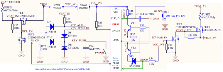
Turn off the mosfet that powers the ESP32 (
M5.disableMainPower();- https://github.com/m5stack/M5EPD/blob/main/src/M5EPD.h#L49). In this mode everything but the external RTC (BM8563) is powered off.In order to wake up from this mode you either need to press the button on the side, or use the external RTC interrupt.
The M5 lib contains a few functions that do exactly this (setup the external RTC to wakeup the board in a few seconds): https://github.com/m5stack/M5EPD/blob/main/src/M5EPD.cpp#L133 -
Hello @tatar-andrei,
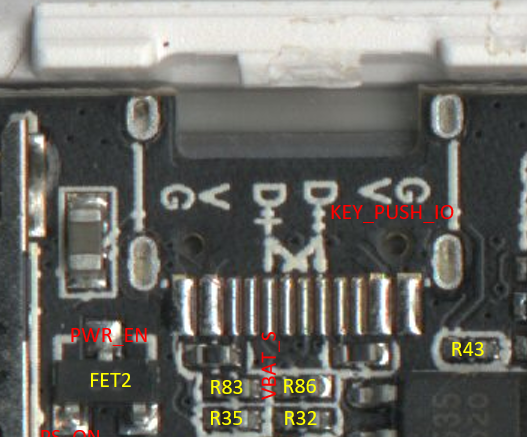
With a supply of 4.2V, U(R35)=11mV, equivalent to 1.1µA for RTC and zener D11current.
Equivalence names table
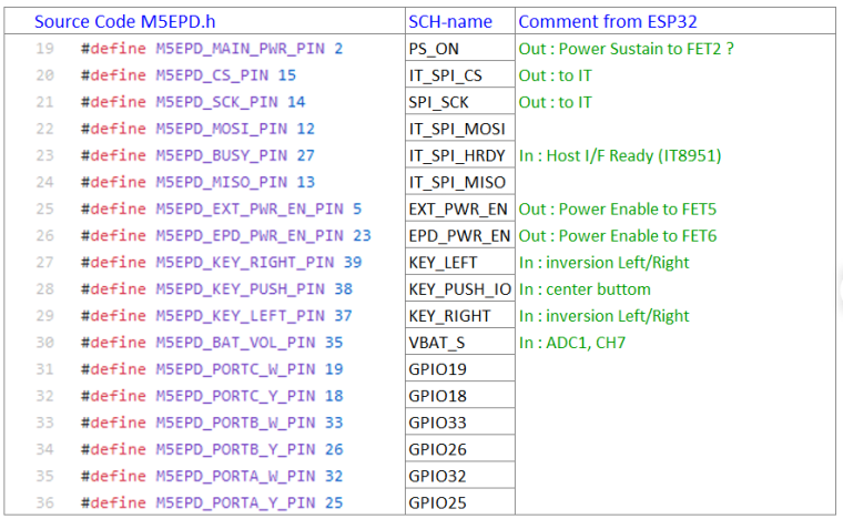
There is inversion between Left and Right, why not having simply called the buttons Top and Bottom?
SYL
-
Hello,
i also made a fisrst compact schema to facilitate understanding
SYL
-
Hello,
If the repository is facing the wheel,
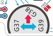
"code source" is true, "SCH-name" is false

SYL
-
Hello,
I completed the schema with VUSB_IN, VSYS and OR fonction with D9,D12
SYL
-
I just received my M5Paper and I can not get a 100% charge? The power consumption also seems high. I am only observing the battery level indicator relative to device use. Is there a problem with the firmware? Is the Wifi function draining the battery prematurely?
-
Hello,
On mine, the maxi level indicator of charge is 86% corresponding to 4.18V
I measured USB current with the program "Factory test" and a serial USB device named "UT25".
The value is 131 mA, without interraction.
I also wrote personal comments about all GPIOs (in french, my native language):
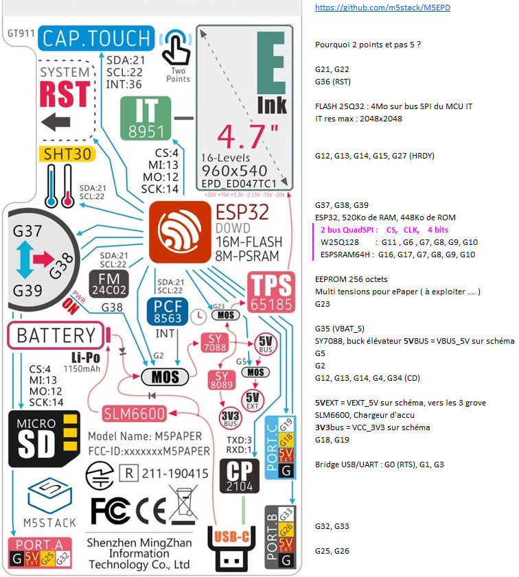
All GPIOs are represented (except non-existent ones : 20, 24, 28, 29, 30, 31)
SYL -
@tatar-andrei
Hello!I was wondering if you could provide some reference for how you got into doze mode/wake on touch? I've been trying for a few days now and for the life of me can't seem to make any meaningful progress.
-
You can check other GT9xx drivers like (http://read.pudn.com/downloads710/sourcecode/embedded/2849392/gt9xx.c__.htm).
I will need to play some more with it. I'll probably post here a link to my repo once I push the code.
-
Hello,
If you want to measure RTC and zener D11 current, i indicate the PCB resistors positions
SYL -
Hello,
As I was saying five days ago,
"I measured USB current with the program "Factory test" and a serial USB device named "UT25".
The value is 131 mA, without interraction."
Since then, I have measured the current according to the different programs :
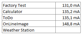
The cause of this excess consumption is IT8951.
An alternative to this component is the 74HC4094D, 8-stage shift-and-store bus register, used as IO extander.
A competitor with the same display consumes 65 mA, i measured to.
SYL -
Hello,
Here is Shift Register schema, the brend is Nexperia.
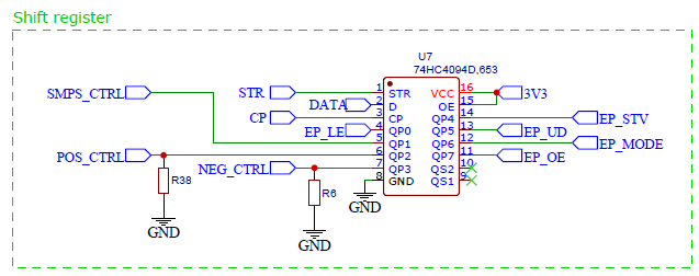
SYL -
@bricox nice work on mapping out the power management system! I've noticed some peculiarities with the charging PMIC (SLM6635, which does not seem to have any english documentation). Specifically, it does not seem to have a proper measuring system set up while charging. Once you connect it to USB power, the indicated battery voltage is actually the charging voltage of the battery, which can be 20-30% higher than the actual (resting) voltage of the battery. This is quite visible if you let the M5Paper with the FactoryTest firmware run out of battery, then connect it to power and head to the factory test screen - the battery indicator will be between 30-50%, and reported battery voltage will be around 3.7-3.8V (which is impossible on a device that was just completely discharged).
The main problem with this is that the battery cutoff voltage for charging seems to be 4.2V - even though the battery is rated 4.35V officially. You can see this, again, on the Factory firmware, by leaving the unit to charge. Once it hits 4.2V stable, charging is cut to that voltage (and the M5Paper displays ~85% battery left). If you disconnect the charger and reconnect it, charging voltage jumps up to 4.35V, however after some time it stops charging (or switches to trickle charging? Not sure about the inner workings of SLM6635), battery voltage slowly drops to 4.2V, and keeps idling there, requiring another disconnect-reconnect to fully charge it again.
I was wondering, since there seems to be some rudimentary control over power management, would it be possible to reset the charging circuit, or somehow fake the disconnect-connect cycle on it? Even if it's a software workaround, it would be nice to be able to properly charge to maximum capacity - and also it would allow to collect appropriate readings while charging.
What I hope for is that the next M5Paper generation gets a better power management solution, even if it's more expensive. Proper PMIC control - especially in low-power applications where one would use an eink screen with an ESP32 for periodic updates - is incredibly important, and right now, by the looks of it, all we have is analog voltage readouts of VBAT, not even the charging/charging complete signals are hooked up (which are arguably important here as well).
Another thing I thought about regarding power saving - would cutting the power to the EXT ports and the EPD display (via methods
disableEPDPower()anddisableEXTPower()) result in any savings?The cause of this excess consumption is IT8951.
An alternative to this component is the 74HC4094D, 8-stage shift-and-store bus register, used as IO extander.
A competitor with the same display consumes 65 mA, i measured to.Uhm... Pardon my ignorance but according to my research the IT8591 is a full-blown EPD timing controller, not just a bus register. I don't see how the 74HC4094D would be an alternative (most definitely not a drop-in replacement).
-
Hi guys
As @fonix232 pointed out the charging / charging complete signals (NSTDBY / NCHRG) of the battery charger are not hooked up in M5Paper.
So I was wondering, what other external indicator are you guys using to know that the battery has been fully charged? What I mean is how to tell the battery is full w/o running some code checking for the battery voltage every now and then.
Thanks
Felix -
@tatar-andrei said in M5Paper EPD power consumption:
... and without any previous state (unless written to FLASH/SD)...you can also save data into M5Papers EEPROM (FM24C02 - 2K-bit(256x8)-EEPROM) during shutdown.
Thanks
Felix -
@fonix232 said in M5Paper EPD power consumption:
battery cutoff voltage for charging seems to be 4.2V
Hello @fonix232
I also thought the charger is only set for 4.2V cutoff voltage due to the fact that the charger IC in the M5Paper schematics is marked as SLM6600. However the charger IC in my M5Paper actually is a SLM6635 which by default has a charging termination voltage of 4.35V according to its data sheet.
Thanks
Felix -
@felmue then how do you explain that charging voltage is 4.35V until the battery reaches 4.2V, when the charging voltage drops to 4.2V as well?
-
Hello @fonix232
a very good question indeed to which I don't have an explanation (yet).
Another question is how accurate the voltage reported by the ESP32 ADC actually is. There also is a voltage divider and some SCALE factor in the factory test firmware. Interestingly the SCALE factor seems to have changed over time:
#define SCALE 0.5//0.78571429Just curious - did you also verify the battery voltage with a multimeter directly connected to the battery?
Thanks
Felix -
Hi guys
today I did a charging experiment with a fully depleted M5Paper battery. After about 2 hours the charger IC switched from charging to standby (according to the two LEDs I've soldered to the corresponding charger IC outputs).
I used a multimeter (connected directly to the battery) to measure the battery voltage. The voltage from the internal ADC, read via
M5.getBatteryVoltage(), was about 5% higher than the voltage read by the multimeter for voltages below 4.2V. Above that the two values were pretty close. The reason for that is the voltage divider (3k / 11k) which when fed with 4.2V produces about 3.3V to the ADC input which is about the maximum a GPIO can take.The highest voltage I've seen on the multimeter was 4.31V before the charging stopped. After which the voltage dropped back to 4.25V. I think that means the charger IC actually is setup for a 4.35V battery, but for some reason doesn't go all the way up to 4.35V.
Update: a possible reason is explained in the datasheet (Google translated):
==========
_______________Charge termination voltage setting The default full termination voltage V FLOAT set inside the chip is approximately 4.35V, but due to the large charging current, the internal resistance of the battery and the line Loss will cause the actual full-charge termination voltage to be lower than this value, resulting in battery failure The law is full enough. SLM6635 by an external resistor RPV to increase V FLOAT of Voltage, used to compensate various losses, or to satisfy different applications Special requirements for voltage.The compensation voltage can be calculated by the following formula:Delta V = I bat (Standby mode) * RPV
If there is no need to compensate the V FLOAT voltage, it is recommended that RPV be set to 1kΩ.
==========
Thanks
Felix -
@tatar-andrei said in M5Paper EPD power consumption:
I did play around more with power down states and I managed to get a light sleep mode with fast wakeup from touch at around ~9mA.
Hello @tatar-andrei
I tried to get the touch into sleep mode by applying the steps outlined in the GT911 programming guide but I don't see any reduction in power consumption.
The steps are:- switch ESP32 interrupt GPIO from input to output and set it low
- issue command 0x05 to address 0x8040
is there anything else that needs to be done? I'd appreciate your insight on that.
Thank you very much in advance.
Cheers
Felix
Hello! It looks like you're interested in this conversation, but you don't have an account yet.
Getting fed up of having to scroll through the same posts each visit? When you register for an account, you'll always come back to exactly where you were before, and choose to be notified of new replies (either via email, or push notification). You'll also be able to save bookmarks and upvote posts to show your appreciation to other community members.
With your input, this post could be even better 💗
Register Login