GPS Module customize about UART port
-
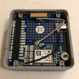
I am going to switch the UART port of GPS Module from UART2 to UART0 or to SoftwareSerial with GPIO 5 and 13. I have a image how to bridge on 1 and 3 or 5 and 13. However, I could not find R1 and R4 for cutting the binding of UART2. Is it done by cutting right side of 17 and 16 by knive?
-
I found this on another forum post http://forum.m5stack.com/topic/175/gps-gsm not sure if it answers your question or not, this is not my area im afraid
-
https://github.com/m5stack/M5-Schematic/blob/master/Modules/module_gps_sch.pdf here is the schematic
-
@lukasmaximus , thanks for your replay both. I am on similar situation.
I am going to force the GPS module escape physically from UART2 to another pins. On the schematic you mentions, it is possible by selecting R1 to R2 or R3, R4 to R5 or R6 (I do not have a plan using PPS). I would like to soldering operation on them. However, R1 and R4 could not be found on PCB. Thus, I am looking for certain information of cutting point on PCB.
-
Maybe it would be helpful for us to know why you need to switch pins, are you combining many modules together? if so perhaps this post would be helpful.
http://forum.m5stack.com/topic/239/howto-m5stack-with-gps-gsm-and-lora-all-at-the-same-time -
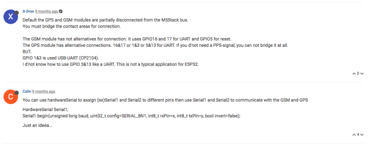
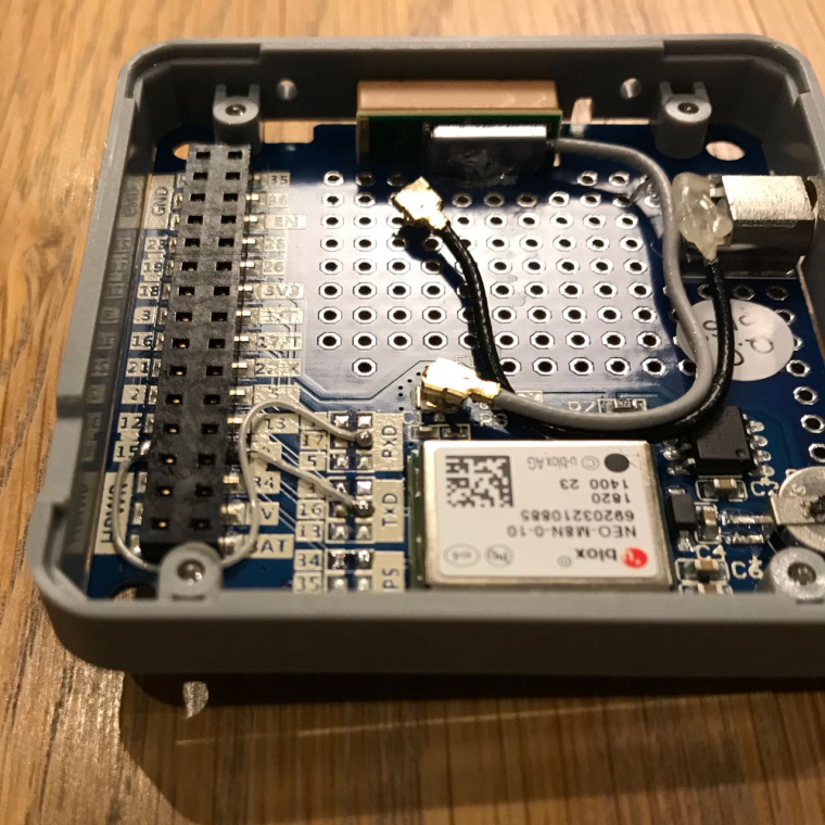
Wow! that is great help for me. I would like to follow the document about GPS Module by "So that means I started by carefully scraping away the traces between the solder bridges marked 16 and 17". Then, I will be able to use GRAY, GPS, PLUS and FINGER (via PORT.C on PLUS) together. Thank you so much.
-
At first, I have tried to use TXD=16 and RXD=17. However, it conflicts downloading a bin by Arduino IDE. On this configuration, the program could be download without GPS Module. Later, stacked GPS Module works.
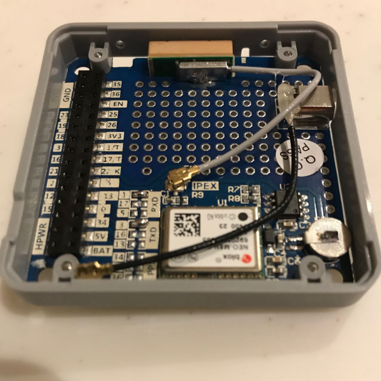
Second, I have tried to use TXD=0, RXD=15 and PPS=34. This configuration is similar to the article by @Rop, but 13 is reserved for PLUS Module. It works with GRAY, GPS, PLUS and FINGER (via PORT.B on PLUS). Thank you!
-
Great, sorry you had to hack around to get all the modules to work together. We are working on improving the design to resolve these issues. What did you make? @tokuhira would love to see your project if you don't mind sharing.