Success!
@robalstona your advice was spot-on. For future reference, here's what I did:
- Disassemble the M5StickC:
- peel the sticker at the bottom from the GPIO pins, do NOT fully remove it
- use a sharp tool to pry away the black GPIO pin block, forward in the direction that the "5V->" arrow indicates on the sticker that was on it.
- open the case with a hex tool
- gently lift and pull out the board
- The battery is attached to 3 different pins: VBATT (red) + GND (black) on the main board and VBATT (red as well) on the extension board/GPIO pins. Cut or desolder the connections on the main board but cut the red wire on the extension board as close as possible to the battery. Then solder the dangling end of this red wire back to VBATT on the main board. Otherwise the new battery cannot be connected via the GPIO pins.
- Now put everything back together in reverse order (first put in the board, then put the GPIO pin cover on, then reattach the sticker)
- Now plug an external 3.7V LiPo battery into the GPIO pins, connected with (-) to GND and (+) to VBATT.
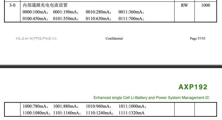
- In my case, the external battery is ~1000 mAh, and I read somewhere that you should charge your lipo batteries with 10% of the mAh rating, so I left the default charging current of 100mA. If using a bigger battery or you want to use higher charge current, then use this command: https://github.com/m5stack/M5StickC/blob/master/src/AXP192.cpp#L470 but keep in mind that you can't use arbitrary currents. You have to pick one of the currents that's compatible with the AXP192 (source: https://usermanual.wiki/Document/axp192xpowers.109566177):
