Issues interfacing MFRC522 (RFID) with M5Stack
-
Hi all,
I'm trying to run the example RFID M5Stack code on a standalone MFRC522 unit (from eBay) but having quite few issues getting the code to work.
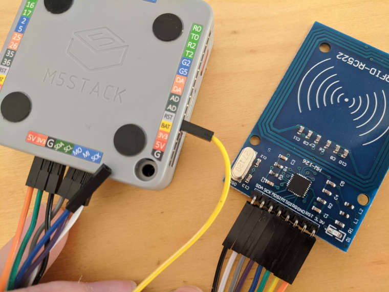
I can download the sample code to the stack and it displays 'M5StackFire MFRC522' on the display but does not read any RFID tags. I first connected the pins:
SDA > SDA
SCK > SCK
MOSI > MO
MISO > MI
GND > G
RST > RST (but on another bus, not sure I can do this)
3.3V > 3V3The tag was not recognised however. It seems the code never executes past mfrc522.PCD_Init(); (Although I'm really not sure where it gets stuck to be honest)
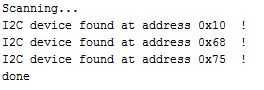
Using the I2C scanner, a device was registered at address 0x10.
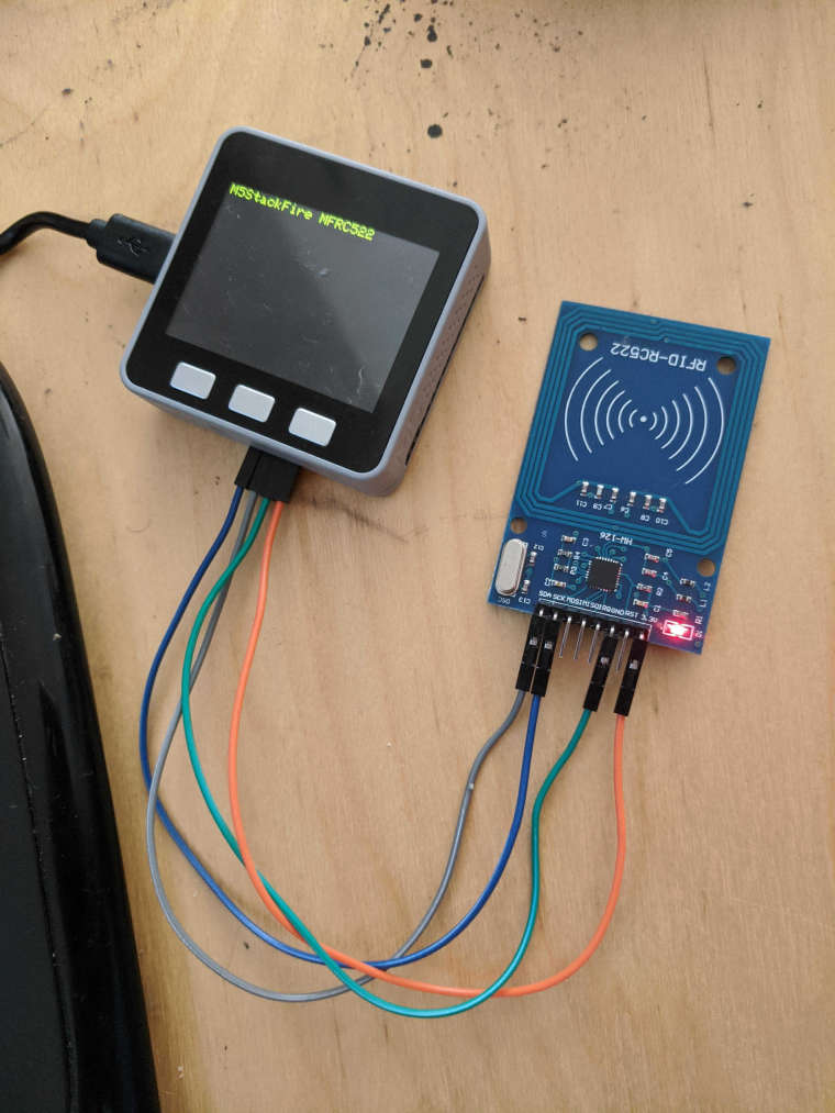
I then realised as the code was using the I2C protocol I only needed to use the lines associated with I2C so wired up the following from the unit to the stack:
SDA, MISO (SCL) , GND, RST and 3.3v
Now the I2C scanner showed no devices attached at all.
Any thoughts on what I may be doing wrong?
Here's a picture of how I've wired it up:
#include "MFRC522_I2C.h" #include <M5Stack.h> // 0x28 is i2c address on SDA. Check your address with i2cscanner if not match. MFRC522 mfrc522(0x10); // Create MFRC522 instance. void setup() { M5.begin(); M5.Power.begin(); M5.Lcd.fillScreen( BLACK ); M5.Lcd.setCursor(0, 0); M5.Lcd.setTextColor(YELLOW); M5.Lcd.setTextSize(2); M5.Lcd.fillScreen( BLACK ); M5.Lcd.setCursor(0, 0); M5.Lcd.println("M5StackFire MFRC522"); Serial.begin(115200); // Initialize serial communications with the PC Wire.begin(); // Initialize I2C mfrc522.PCD_Init(); // Init MFRC522 ShowReaderDetails(); // Show details of PCD - MFRC522 Card Reader details Serial.println(F("Scan PICC to see UID, type, and data blocks...")); M5.Lcd.println("Scan PICC to see UID, type, and data blocks..."); } void loop() { // Look for new cards, and select one if present if ( ! mfrc522.PICC_IsNewCardPresent() || ! mfrc522.PICC_ReadCardSerial() ) { delay(50); return; } // Now a card is selected. The UID and SAK is in mfrc522.uid. // Dump UID Serial.print(F("Card UID:")); M5.Lcd.println(" "); for (byte i = 0; i < mfrc522.uid.size; i++) { Serial.print(mfrc522.uid.uidByte[i] < 0x10 ? " 0" : " "); Serial.print(mfrc522.uid.uidByte[i], HEX); M5.Lcd.print(mfrc522.uid.uidByte[i] < 0x10 ? " 0" : " "); M5.Lcd.print(mfrc522.uid.uidByte[i], HEX); } Serial.println(); } void ShowReaderDetails() { // Get the MFRC522 software version byte v = mfrc522.PCD_ReadRegister(mfrc522.VersionReg); Serial.print(F("MFRC522 Software Version: 0x")); Serial.print(v, HEX); if (v == 0x91) Serial.print(F(" = v1.0")); else if (v == 0x92) Serial.print(F(" = v2.0")); else Serial.print(F(" (unknown)")); Serial.println(""); // When 0x00 or 0xFF is returned, communication probably failed if ((v == 0x00) || (v == 0xFF)) { Serial.println(F("WARNING: Communication failure, is the MFRC522 properly connected?")); } } -
Your MFRC522 uses same chip as the M5Stack RFID unit.
You did the right thing hooking it up to Vcc 3.3V (The M5Stack unit has a 3.3V voltage regulator build in):Try to hook it up only to I2C (SDA to SDA, SCL to SCK, GND to GND, 3.3V to 3.3V, +/- the red Grove A connector but with 3.3V for Vcc instead of 5 V, otherwise you will probably brick the board). Then run the UIFlow/Blockly I2C scan and look if it responds to the 0x28 (decimal 40) address. If you are lucky and you can address the board on the wire I2C bus, you can either use UIFlow/Blockly or the M5Stack Arduino code as described for their RFID unit.
You forgot to "#include <Wire.h>" library in your Arduino code. The way you hooked up your board the ESP32 doesn't know how to address it (serial, SPI or I2C ?). The M5Stack library uses I2C for their RFID unit. -
Hi Crami,
Thanks so much for the reply. I've tried to wire up the unit as you described. Unfortunately I cannot make use of the groove connector because the jumper wire connectors are too large to all fit in the socket and I don't have any other wires.
Instead I've wired:
SDA -> SDA,
SCL -> SCK (Instead of SCL/MISO),
3V3 -> 3.3V and G -> GND.As for the code, it does #include <wire.h> (seems I cut if off the embed accidentally!)
Unfortunately, still doesn't get past the println below:
I should also mention there is a high pitched buzzing coming from the m5stack?
Here's a the output from the serial plotter too:
-
It appears, that you can't address your RFID reader over I2C. Ordering a MFRC522 from an eBay source you never know what you get. The safest way of an external sensor to communicate with an M5Stack is communicating by I2C. With I2C the master can communicate with up to 127 different slaves.
The SPI serial communication is between one master and a single slave. So, in addition to the communication lines (MOSI, MOSI, SCK) you will need a CS line selecting the slave (only one at a time !!! ) and also a RST and maybe an IRQ line ! ESP32 devices comming from different manufacturers often have hooked up their own SPI peripherals controlled by their dedicated firmware. That's why programming in arduino you must carefully select which board you are using (M5Stack, M5Stick, HeltecLoRa, WemosOLED ...) otherwise it's a big chance to brick the LCD display of the M5Stack and maybe the ESP32 itself. I'm just experimenting with my TTGO WiFi LoRa 32. On the Pinout Diagram they are noting: "Pins with the red arrow are used by the on-board OLED or LoRa, they must not be used for any other purpose unless you konw what you are doing!".
I'vd hooked up my M5Stack RFID unit to my M5Stack, read the ID of RFID devices and stored and retreived data (without noise from the speaker) in UIFlow.
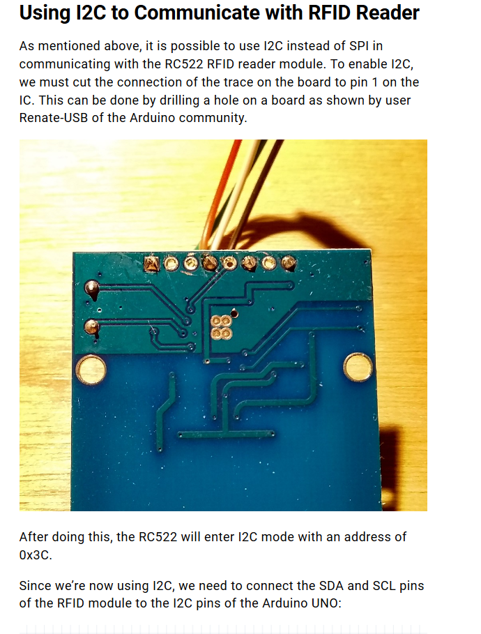
If you want to use your eBay RFID the best thing would be to convert it to an I2C device (address 0x3c) as descibed in
https://www.teachmemicro.com/arduino-rfid-rc522-tutorial/
Here is a picture how they have done it:
-
Hi Crami,
Many thanks for your response. Unfortunately I don't have a drill so I can't enforce I2C mode. I've tried to change the code to use SPI instead. Now I can't get it to write at all and receive the following errors:
#include "MFRC522.h"
#include <M5Stack.h>

// 0x28 is i2c address on SDA. Check your address with i2cscanner if not match.
MFRC522 mfrc522(0x15, 0x02);   // Create MFRC522 instance.

void setup() {
  M5.begin();
  M5.Power.begin();
  M5.Lcd.fillScreen( BLACK );
  M5.Lcd.setCursor(0, 0);
  M5.Lcd.setTextColor(YELLOW);
  M5.Lcd.setTextSize(2);

  M5.Lcd.fillScreen( BLACK );
  M5.Lcd.setCursor(0, 0);
  M5.Lcd.println("M5StackFire MFRC522");
  Serial.begin(115200);           // Initialize serial communications with the PC
  SPI.begin();                   // Initialize I2C

  mfrc522.PCD_Init();             // Init MFRC522
  ShowReaderDetails();            // Show details of PCD - MFRC522 Card Reader details
  Serial.println(F("Scan PICC to see UID, type, and data blocks..."));
  M5.Lcd.println("Scan PICC to see UID, type, and data blocks...");
}

void loop() {
  // Look for new cards, and select one if present
  if ( ! mfrc522.PICC_IsNewCardPresent() || ! mfrc522.PICC_ReadCardSerial() ) {
    delay(50);
    return;
  }

  // Now a card is selected. The UID and SAK is in mfrc522.uid.

  // Dump UID
  Serial.print(F("Card UID:"));
  M5.Lcd.println(" ");
  for (byte i = 0; i < mfrc522.uid.size; i++) {
    Serial.print(mfrc522.uid.uidByte[i] < 0x10 ? " 0" : " ");
    Serial.print(mfrc522.uid.uidByte[i], HEX);
    M5.Lcd.print(mfrc522.uid.uidByte[i] < 0x10 ? " 0" : " ");
    M5.Lcd.print(mfrc522.uid.uidByte[i], HEX);
  }
  Serial.println();

}

void ShowReaderDetails() {
  // Get the MFRC522 software version
  byte v = mfrc522.PCD_ReadRegister(mfrc522.VersionReg);
  Serial.print(F("MFRC522 Software Version: 0x"));
  Serial.print(v, HEX);
  if (v == 0x91)
    Serial.print(F(" = v1.0"));
  else if (v == 0x92)
    Serial.print(F(" = v2.0"));
  else
    Serial.print(F(" (unknown)"));
  Serial.println("");
  // When 0x00 or 0xFF is returned, communication probably failed
  if ((v == 0x00) || (v == 0xFF)) {
    Serial.println(F("WARNING: Communication failure, is the MFRC522 properly connected?"));
  }
}
Errors:
Arduino: 1.8.12, Board: "M5Stack-Core-ESP32, QIO, 80MHz, Default, 921600, None"
Sketch uses 356605 bytes (27%) of program storage space. Maximum is 1310720 bytes.
Global variables use 17628 bytes (5%) of dynamic memory, leaving 310052 bytes for local variables. Maximum is 327680 bytes.
esptool.py v2.6
Serial port COM3
Connecting....
Chip is ESP32D0WDQ6 (revision 1)
Features: WiFi, BT, Dual Core, 240MHz, VRef calibration in efuse, Coding Scheme None
Uploading stub...
Running stub...
Stub running...
Changing baud rate to 921600
Changed.
Configuring flash size...
Warning: Could not auto-detect Flash size (FlashID=0x0, SizeID=0x0), defaulting to 4MB
Compressed 8192 bytes to 47...Writing at 0x0000e000... (100 %)
Wrote 8192 bytes (47 compressed) at 0x0000e000 in 0.0 seconds (effective 6553.6 kbit/s)...A fatal error occurred: Timed out waiting for packet header
A fatal error occurred: Timed out waiting for packet headerCan you spot anything I may be doing wrong?
-
I2C # SPI
You forgot to use #include <SPI.h> in your arduino code. So the code compiled for I2C interface.Beware using the wrong pins for external SPI deviceon your M5Stack. You may brick your display. Interfacing to an external a SPI peripheral device you should use pins which are not in conflict with the pins used for M5Stack internals, as I already wrote in my comments on SPI Interfacing a few days ago:
http://community.m5stack.com/topic/1845/micropython-spi/8
You should keep it as they are saying on my spec sheet for the Heltec ESP32 LoRa board: "Pins used by on board OLED or LoRA must not be used for other purpose unless you know what you are doing !
Accordingly, on the M5Stack you should only use the pins marked in blue.