EXT.IO Unit and UIFlow 1.4.5.1
-
I'm experimenting with M5Stack products (core, stick, atom matrix) and various I2C units (PbHUB, EXT.IO and Color) trying to use UIFlow and Blockly exclusively (instead of Arduino):
As describet in the data sheets, all M5Stack I2C units have different fixed I2C addresses , PbHUB at 0x61, EXT.IO at 0x27. According to their M5Stack data sheets you can change the corresponding I2C addresses by modifying the address-pins of the EXT.IO unit PCA9554PW (0x20-0x27) or by flashing a new firmware to the PbHUP 328 microcontroller assigning any new I2C firmware address you want (0x00-7F) into the arduino code. By the way, I did that: flashing the firmware of the PbHUB to an arduino UNO. It worked and it behaved as a PbHUB in blockly. Showing that the communication between the master (M5Stack devices) and the slaves (PbHUB, EXT.IO) is working, I set up the simplest output experiment programming microcontrollers: letting a LED blink on output pin 1 of the slave (The basic Arduino "Hello Word" experiment): I hooked up a LED with a 470 Ohm protection resistor in serial between output 1 (IO1) and GND. The goal of my experiments was trying to set up the BLINK experiment in UIFlow/Blockly first using the "add UNIT" utility, later on using the I2C command of the advanced section of UIFlow/Blockly. I waned to use the latter beeing able hooking up grove type I2C sensors to port A of M5Stack masters, which are not (yet) available or defined for M5Stack block coding. One such application I'm working on, is the DS2482 I2C to onewire chip, which could be used to hook up the popular DS18B20 Sensor to all M5Stack devices having a I2C PortA using UIFlow blocks and connecting the sensors to the I2C PortA instead of using another M5Stack port mandatory forh the arduino or mycropython library. One wire devices also let you commuicate with sensors up to 1000m away, the maximum distance for I2C devices is only 100cm if you are lucky !For my experiments, I flashed the newest UIFlow 1.4.5.1 to my M5Stack core (black). It allows you to do the debugging on its screen. I downloaded the UIFlow/Blockly programs by WiFi or USB (comx Port) .
In these comments I will show you step by step how it worked programming the EXT.IO.
The first step was to attach the EXT.IO unit to portA and with short UIFlow program acting as a I2C scanner. The results showed that the i2C bus and the EXT.IO unit were responding. I used label0 on the M5Stack display:
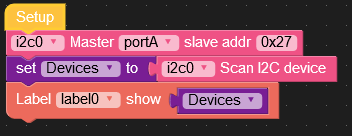
The dsplay showed "(39, 117)", 0x27 and 0x75 in hex, equivalent to the I2C addresses of the EXT.IO unit and IP5306 IC are responding .Then I added the EXT.IO unit in Blockly without modifying the code above:
Downloading the program I got following error code on the M5Stack core display:
ERROR
I2C bus error (-1)
So apparently something went wrong! Looking at the micropython code I discovered, that adding the EXT.IO unit, in addition to the code scanning and displaying the I2C devices following line was added to the Python program:ext_io2 = unit.get(unit.EXT_IO, unit.PORTA)
Because my previous experiments with the color hub and the PbHUB didn't show this behavior, I figured out, that there must be a bug in the unit.get(unit.EXT_io,unitPORTA) library used in UIFlow 1.4.5.1. I erased my M5Stack core with the M5Stack burner (in Windows 10) and reflashed the core with UIFlow 1.4.5 and reloaded the program. Running the program showed no errors and worked as expected. So the bug for the EXT.IO unit library is only in the new UIFlow 1.4.5.1 and not in the 1.4.5 library.
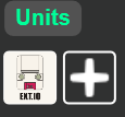
After that, I could finish my "Hello World" IO Test as mentioned above writing following code:
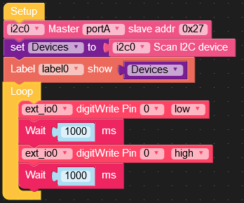
In the next step, I wanted to say "Hello"/Blink using the advanced I2C blocks you also can usecommunicating with I2C devices using only blocks in UIFlow. You communicate with the I2C devices using their addresses and putting data in the appropriate registers.Looking at the data sheet for the PCA9554PW chip present in the EXT.IO unit, I used following data:
- Address : 0x27
- Configuration Register: 0x03 (ones for input zeroes for input)
- Polarity Data Register: 0x02 (set to 0 by default, not used in this context))
- Output Data Register: 0x01 (I used this for output to the blink pin)
- Read Data Register: 0x00
For my "Hello"/IO Blink at pin1 I had to set pin 1 of the PCA9554PW to an output in the configuration register (0x03), and the sending zeros(0x00) (Led off) and ones(0x01) (Led on) to the output data register(0x01). Here is my UIFlow code (for UIFlow 1.4.5):
So far everything worked. I reflashed my M5Stack core with UIFlow 1.4.5.1 and I had no problem executing the code ("Hello" LED blinking) with the newest firmware. So the problem seems to be in the library ! I hope M5Stack will fix in the one of thenext updates (as well as with the color unit library, where I showed in another community blog how you could fix the readings of RGB using an appropriate UIFlow.Another feature I didn't like with the UIFlow I2C blocks is that you have to enter the adresses, registers and bytes as constant hex numbers into the advanced I2C blocks. It would be nice to use variables instead constants.I fixed this my way using the feature in UIFlow defining
Execute blocks, where you can insert your own micropython code into custom created blocks.Looking at the block for the blink code:
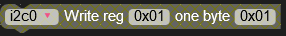
in micropython this translates toi2c0.write_u8(0x01, 0x01)
I now added two variables <Led1off> and <Led1on> to tmy blocks, defined two execute blocks:
code into the corresponding execute blocks:
i2c0.write_u8(0x01, Led1off) and
i2c0.write_u8(0x01, Led1on)
Then setting <Led1off> to 0 and <Led1on> to 1 did the work. Here is the final code: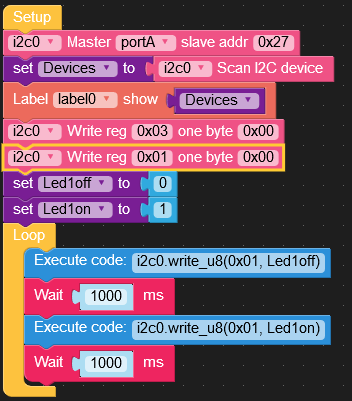
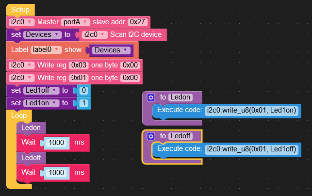
You can also do some pretty"blocking" putting the IO commands in functions:
Hope my contributions to the community were useful !
crami25 -
@crami25 said in EXT.IO Unit and UIFlow 1.4.5.1:
I'm experimenting with M5Stack products (core, stick, atom matrix) and various I2C units (PbHUB, EXT.IO and Color) trying to use UIFlow and Blockly exclusively (instead of Arduino):
As describet in the data sheets, all M5Stack I2C units have different fixed I2C addresses , PbHUB at 0x61, EXT.IO at 0x27. According to their M5Stack data sheets you can change the corresponding I2C addresses by modifying the address-pins of the EXT.IO unit PCA9554PW (0x20-0x27) or by flashing a new firmware to the PbHUP 328 microcontroller assigning any new I2C firmware address you want (0x00-7F) into the arduino code. By the way, I did that: flashing the firmware of the PbHUB to an arduino UNO. It worked and it behaved as a PbHUB in blockly. Showing that the communication between the master (M5Stack devices) and the slaves (PbHUB, EXT.IO) is working, I set up the simplest output experiment programming microcontrollers: letting a LED blink on output pin 1 of the slave (The basic Arduino "Hello Word" experiment): I hooked up a LED with a 470 Ohm protection resistor in serial between output 1 (IO1) and GND. The goal of my experiments was trying to set up the BLINK experiment in UIFlow/Blockly first using the "add UNIT" utility, later on using the I2C command of the advanced section of UIFlow/Blockly. I waned to use the latter beeing able hooking up grove type I2C sensors to port A of M5Stack masters, which are not (yet) available or defined for M5Stack block coding. One such application I'm working on, is the DS2482 I2C to onewire chip, which could be used to hook up the popular DS18B20 Sensor to all M5Stack devices having a I2C PortA using UIFlow blocks and connecting the sensors to the I2C PortA instead of using another M5Stack port mandatory forh the arduino or mycropython library. One wire devices also let you commuicate with sensors up to 1000m away, the maximum distance for I2C devices is only 100cm if you are lucky !For my experiments, I flashed the newest UIFlow 1.4.5.1 to my M5Stack core (black). It allows you to do the debugging on its screen. I downloaded the UIFlow/Blockly programs by WiFi or USB (comx Port) .
In these comments I will show you step by step how it worked programming the EXT.IO.
The first step was to attach the EXT.IO unit to portA and with short UIFlow program acting as a I2C scanner. The results showed that the i2C bus and the EXT.IO unit were responding. I used label0 on the M5Stack display:
The dsplay showed "(39, 117)", 0x27 and 0x75 in hex, equivalent to the I2C addresses of the EXT.IO unit and IP5306 IC are responding .Then I added the EXT.IO unit in Blockly without modifying the code above:
Downloading the program I got following error code on the M5Stack core display:
ERROR
I2C bus error (-1)
So apparently something went wrong! Looking at the micropython code I discovered, that adding the EXT.IO unit, in addition to the code scanning and displaying the I2C devices following line was added to the Python program:ext_io2 = unit.get(unit.EXT_IO, unit.PORTA)
Because my previous experiments with the color hub and the PbHUB didn't show this behavior, I figured out, that there must be a bug in the unit.get(unit.EXT_io,unitPORTA) library used in UIFlow 1.4.5.1. I erased my M5Stack core with the M5Stack burner (in Windows 10) and reflashed the core with UIFlow 1.4.5 and reloaded the program. Running the program showed no errors and worked as expected. So the bug for the EXT.IO unit library is only in the new UIFlow 1.4.5.1 and not in the 1.4.5 library.
After that, I could finish my "Hello World" IO Test as mentioned above writing following code:
In the next step, I wanted to say "Hello"/Blink using the advanced I2C blocks you also can usecommunicating with I2C devices using only blocks in UIFlow. You communicate with the I2C devices using their addresses and putting data in the appropriate registers.Looking at the data sheet for the PCA9554PW chip present in the EXT.IO unit, I used following data:
- Address : 0x27
- Configuration Register: 0x03 (ones for input zeroes for input)
- Polarity Data Register: 0x02 (set to 0 by default, not used in this context))
- Output Data Register: 0x01 (I used this for output to the blink pin)
- Read Data Register: 0x00
For my "Hello"/IO Blink at pin1 I had to set pin 1 of the PCA9554PW to an output in the configuration register (0x03), and the sending zeros(0x00) (Led off) and ones(0x01) (Led on) to the output data register(0x01). Here is my UIFlow code (for UIFlow 1.4.5):
So far everything worked. I reflashed my M5Stack core with UIFlow 1.4.5.1 and I had no problem executing the code ("Hello" LED blinking) with the newest firmware. So the problem seems to be in the library ! I hope M5Stack will fix in the one of thenext updates (as well as with the color unit library, where I showed in another community blog how you could fix the readings of RGB using an appropriate UIFlow.Another feature I didn't like with the UIFlow I2C blocks is that you have to enter the adresses, registers and bytes as constant hex numbers into the advanced I2C blocks. It would be nice to use variables instead constants.I fixed this my way using the feature in UIFlow defining
Execute blocks, where you can insert your own micropython code into custom created blocks.Looking at the block for the blink code:
in micropython this translates toi2c0.write_u8(0x01, 0x01)
I now added two variables <Led1off> and <Led1on> to tmy blocks, defined two execute blocks:
code into the corresponding execute blocks:
i2c0.write_u8(0x01, Led1off) and
i2c0.write_u8(0x01, Led1on)
Then setting <Led1off> to 0 and <Led1on> to 1 did the work. Here is the final code:You can also do some pretty"blocking" putting the IO commands in functions:
Hope my contributions to the community were useful !
crami25Excellent and very useful posting. I am also exploring the UIFLOW using M5 Cores (Fire, Stick-C, and Atom) with M5 standard Units and Hats. Previously I used Arduino IDE. I have a lot of questions, but the first one is related to your successful experiment result on flashing an Arduino UNO to behave as an PbHub: (1) Did you flash the UNO using Arduino IDE? (2) I suppose you connect the M5 core I2C port with the SDA and SCL of UNO to communicate, but how about the voltage difference between the M5 (3.3 V) and UNO (5.0 V)? Could you explain in more detail on this issue?
-
We already discussed this topic 7 months ago in
=> 5V input concern on M5StickC :
where I posted my first comment in the M5Stack community blog.
Here are some additional explenations:
If you look at the schematics for M5Stack modules and units using Atmega 328 slaves:
-> All Atmegas 328 are powered by 5V Vcc.
-> The Makey unit, the Joystick unit and the Servo Module use 470 Ω resistors between the SCL/SDA lines and the corresponding grove connector or the SCL/SDA lines M5Stack_BUS (pin 18/GPIO22 and pin 17/GPIO21, common standard for the ESP32).
-> In the pbHUB 328 SCL/SDA are connected directly to the grove connector (red) without the protecting in series resistors.In normal cases connecting 5V devices and 3.3V devices communicating via the I2C bus without protection causing no problems (bricking the ESP32) can be explained how I2C communication works:
If you connect a pin of a 5V device (eg the 328) defined as an output and as high (1) to an output pin of a 3.3 V device (ESP32) defined as low(0), the 3.3V device tries to sink the current. The maximum current the ESP32 can sink is only 12mA (https://esp32.com/viewtopic.php?t=2384). The maximum output current the 5V-328 can provide 20mA and more. If the current is higher, the output Voltage will drop. Each condition is more than an otput pin of the ESP32 can sink. So the possibility bricking parts of or the whole of the ESP32 is high. Connecting a 470 Ω resistor between the to pins limits the worst case current to 8mA, which is safe for both devices in case of bad programming: It's also good practice connecting the "hello world" blinking led using a current limiting resistor to Vcc or GND in order to avoid stress on the diode (you don't now how much max current it can draw) or the output pin (you don't know how much max current it can provide. There are also some bad examples sticking the LED directly into the UNO header between IO13 and GND! https://github.com/LequiosCreative/arduino-blink-led ).
On an I2C communication bus you normally only have one master and one or more slaves. The master always has the command on the I2C bus: It clocks the SCL line (Clock line) using a pin as an output. The SDA line is used transferring commands and datas to and from the slaves. At the beginning of a transmission the master sends an address and the appropriate commands to a slave and the SDA pin of the master is set as an output. If the master expects datas transmitted from a slave after sending a "read input values" command, the master switches its pin for the SDA line to an input allowing the slave sending data over the sda line switching its SDA pin from an input to output. So, under normal conditions, the SDA lines of the master and the slave, if the protocol is implemented correctly, never should be simultaneously configured as outputs.
So good practice would be to insert 470 Ω resistors in the SCL/SDA lines as also recommended in the I2C hardware specifications. Thank you for your question. From now on I will always use my 328s (plain 328, UNO, micro, mini, attinys 85/86/861) communicating on the I2C bus with ESP82/8266 devices using the protective resistors. Comment: According to the I2C protocol, a slave is allowed to pull the clock line low if the slave isn't ready sending data, overriding the master SCL line ! In this case there would be a problem for master/slaves combination communicating on different voltage levels.
Suggestion to M5Stack team: I opened the PbHUB hub and found the two 103 SMD (10 kΩ)
pullup resitors connected to the SCL/SDA lines but nowhere any 470 SMD (470 Ω) resistors on their printed circuit board. So it seems that their schematic is correct ( https://docs.m5stack.com/#/en/unit/pbhub). In my opinion, in their future designs they should add the protective resistors recommended as they already have implemented in their other hubs and modules using the Atmega328 as an I2C slave.Add: You can find a better explanation how the I2C communication works here : https://howtomechatronics.com/tutorials/arduino/how-i2c-communication-works-and-how-to-use-it-with-arduino/
Add2: If You want to build an I2C arduino slave from scratch, here is step by step tutorial:
https://roboticsbackend.com/raspberry-pi-master-arduino-slave-i2c-communication-with-wiringpi/
You can use your M5Stack device instead of the RasPi.
In their example, they are connecting the UNO 5V I/O pins without protecting resistors and pullup resistors (as I did) directly to the RasPi so called "non 5V tolerant 3.3V" GPIO pins ! But they drew the same conclusions as I did above:
""You should really pay attention when you connect 2 pins between those boards. Usually you’d have to use a level converter between 3.3V and 5V. But in this specific case we can avoid using one.
If the Raspberry Pi is configured as a master and the Arduino as a slave on the I2C bus, then you can connect the SDA and SCL pins directly. To make it simple, in this scenario the Raspberry Pi will impose 3.3V, which is not a problem for the Arduino pins."" -
@crami25 Thanks for the comprehensive reply. It really helps to deepen my understanding. As you pointed out, I always check the M5 Unit's schematic first to assure the protective resistors when I connect the Units to an ESP developing board.
Hello! It looks like you're interested in this conversation, but you don't have an account yet.
Getting fed up of having to scroll through the same posts each visit? When you register for an account, you'll always come back to exactly where you were before, and choose to be notified of new replies (either via email, or push notification). You'll also be able to save bookmarks and upvote posts to show your appreciation to other community members.
With your input, this post could be even better 💗
Register Login