NB-IoT usage and specs
-
Hi,
I am wondering how exactly the NB-IoT module is supposed to be used. It has a "Power button", and it seems to be neccessary to have it pressed for a few seconds/times/depends on the moon to be able to communicate with the module at all (I am using the default UART). Are the usage instructions or more examples somewhere? Also, the schematics indicate that the power line is connected to GPIO2, is this correct? Is there a reliable way to switch on the module via GPIO2 then (I could not get that working)? A specs document of the used "M5311" would be very helpful with this, but it is nowhere to be found (only a manual of the AT commands is available). Last question: I would like to use TinyGSM, is the module compatible with any of the predefined modems or do I have to extend TinyGSM?
Any help on this is appreciated!
Thorsten. -
Hi Thorsten,
Same issue here. The example code doesn't work at all: https://github.com/m5stack/M5-ProductExampleCodes/blob/master/Module/NB_IOT/Arduino/NB_IOT.ino
Code refers pin 5 in the setup and that pin is used in the schematics for serial line receive (and actually it is not connected as zero ohm resistor is missing). I think this code is just some kind of copy other M5Stack module examples and not suitable for this.
This module seems to be dead even I try to switch on power and reset as it have been guided in their website:
Power Operation:
Power On: GPIO2 stay HIGH for 2s
Power Off: GPIO2 stay HIGH for 8s
Power On: Button long-press for 2s
Power Off: Button long-press for 8s
Reset module: GPIO26 HIGHIn code level I have used following in setup:
pinMode(2, OUTPUT);
pinMode(26, OUTPUT);digitalWrite(2, 1);
delay(3000);
digitalWrite(2, 0);digitalWrite(26, 0);
delay(500);
digitalWrite(26, 1);
delay(500);
digitalWrite(26, 0);When I send AT command to module. Sometimes it reply empty characters, but I am not sure is that just a noise.
Any help is appreciated!
Best regards, Jarkko
-
Got support from M5Stack team.
M5Stack Fire has occupied GPIO16 / 17 to connect with the PSRAM by default, it's conflict with TXD / RXD (GPIO16, GPIO17) of NB-IoT module. Therefore, when using the GPS module with the M5Stack Fire, you might have to cut the TXD and RXD from NB-IoT module and wire fly to another set of UART pin, if you gonna use the PSRAM.
What you need to do is that,
- Cut the TXD and RXD from NB-IoT module;
- Jump wire to other GPIOs, for example TX to GPIO5, RX to GPIO12;
- Change the code according to the new GPIOs;
Serial2.begin(115200, SERIAL_8N1, 12, 5); - Upload to play.
Cut is easy to do as there are ready made 0-ohm resistors that you can use.
Tested and this works!
-
@jmakiv does it mean you have a functioning dataconnection?
If you do, would you e willing to give some more hints?
Thanks! -
This post is deleted! -
@jmakiv I would like to know it too, do you have a functional data connection? My board doesn't respond to any AT commando i put in.
-

Hi,
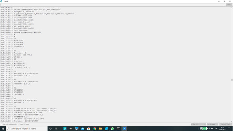
I am using the nb-iot module with m5stack. The program is https://github.com/m5stack/M5-ProductExampleCodes/blob/master/Module/NB_IOT/Arduino/NB_IOT.inoBut I can't understand the mistake.
Can someone help me?