TermTab5
-
TermTab5 is an Arduino/ESP32 touchscreen terminal firmware project with a VT100-style terminal core, on-screen keyboard, touch-driven menu system, board abstraction layer, settings persistence, Wi-Fi helpers, and optional screensaver-style animations.
The codebase targets M5 Tab5 and related ESP32 display hardware, while keeping a substantial part of the terminal and UI stack reusable and host-testable.
Demo video
In this video is a custom made Z80-based handheld retro computer running RomWBW with Tab5 as a screen. -
Re: TermTab5
Hello,Thank you for this great program. There is one thing that is unclear to me. How do I establish a serial connection with an external device? I plan to connect the terminal to a Forth computer and want to use the serial connection for that.
Which pins/connector did you use for your own computer?
I hope you can help me with this.
Kind regards, Jan -
@Powersoft Hi!
Not visiting this forum very often, I'd have to see if notifications can be enabled.So, to your question, if you download Tab5 schematics there's M5_BUS connector on page 4. You need pins 13 (aka U0RXD, aka G3) and 14 (aka U0TXD, aka G1). They use 3V3 logic levels but are 5V tolerant as per Espressif themselves (and my thorough testing).
Feel free to ask more questions. -
@h0lmes
Thanks for your information, but i'm a bit confused. I asumed that I must used the black 30p connector on the backside. Wich pins on this connector I should use? Is it not posible to use the grove connector with pins G53 ,G54.With kind regards,
Jan
-
You should ythink about allowing the user to specify the port to use, especially on the Tab5, which has lots of IO ports.
Also; your (or your AI coder) seems to be confused.
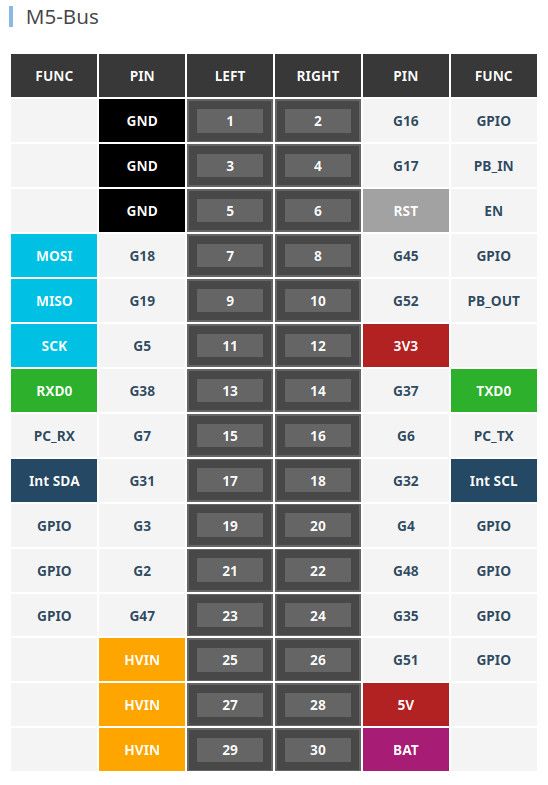
pin 13 = U0TXD = G37
pin14 = U0RXD = G38Not G3/G1
The P4 can basically mux hardware Serial onto any pin combo. And software serial can handle any pins that dont mux.
Pins G49 and G50 are on ExtPort1 on the side of the unit, (so are G0 and G1, but these should be avoided unless you understand how G0 is used at boot time).
There is a RS485 port on pins G20/G21/G34 (TX/RX/Dir) that would also be sensible to support.
And, of course, G53 and G54 on the grove connector (port-A) can be used, by default this is the User I2C bus (I2C1). If you don't want to use any external I2C peripherals then it is a good choice.
-
This post is deleted! -
This post is deleted! -
@easytarget I assume you did not read my message carefully. G1/G3 are in the PDF Schematics
-
@Powersoft Hi!
You can easily use any pins with SoftwareSerial, though I did not test it. One of my primary goals was to make it work fast (which is not what you usually expect from software serial).
Can you do it yourself? Or maybe use a GhatGPT (point it to the main .ino file and ask to change to pins you want).
If you encounter any problems message me, I'll try to find some time to do tests. -
@h0lmes Software Serial is best left for smaller devices with limited IO mapping. For any of the recent ESP32 chips you should one of the hardware UARTS, the P4 has six of them!
You can mux any GPIO pin to any hardware UART. That way you get speed with no cpu load, and the option to do DTS/CTS etc by just specifying the extra pins.
https://docs.espressif.com/projects/arduino-esp32/en/latest/tutorials/io_mux.html#peripheral-table
However if (and I have not looked at the code) you just use the default esp functions it will default to a hardware UART if it can and only use soft serial as needed, so you may be good anyway ;-)
-
@h0lmes
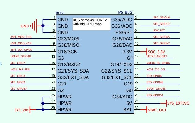
Actually I was ignoring that; I am using the actual P5 GPIO pin numbers for clarity.If you look at the image I pasted, which is from the Tab5 main documentation, you can see that it also uses the real GPIO pin numbers.
The M5_BUS uses pin names based on the original M5Stack, and the schematic shows the M5_BUS pin names there, and this is very important if interfacing to other stack modules! But the actual GPIO numbers are what you need in your terminal code. Using the M5_BUS labels just confuses things.
So; I prefer to use the actual P5 GPIO pin numbers, rather than having to do a mental 'GPIO pin X == M5_BUS pin Y' conversion every time.
-
@h0lmes
Hello, thanks for your information, please can you point me where to find in the code I should search for the pinnumbers, i have search a lot of time but no result.
With kindley regards
Jan -
@Powersoft Hi!
I have updated the project and added a feature flag at line 26 of PlatformConfig.hpp. If you uncomment it the source compiles with grove connector as a UART.
As can be seen at TermTab.ino lines 136-137: pin 53 is TX and pin 54 is RX.
You are welcome. -
@easytarget
It seems to me that the M5 team could've done a better job with the Tab5 schematics to avoid all this potential confusion.
Thanks for taking the time to point out all those details. -
I didn't implement those pins selectable in software because it is intended for use on almost any ESP-based hardware.
Though if I have a good idea on how to do it without sacrificing portability I might add it later. -
@h0lmes
Thanks for the modification of your program.
First test run as a charm.
Can the terminal work with vt100 sequeces?
With kindley regards
Jan -
@Powersoft
Yes, you can find ESC sequence handling at lines 1515-1927 of Terminal.cpp.
Hello! It looks like you're interested in this conversation, but you don't have an account yet.
Getting fed up of having to scroll through the same posts each visit? When you register for an account, you'll always come back to exactly where you were before, and choose to be notified of new replies (either via email, or push notification). You'll also be able to save bookmarks and upvote posts to show your appreciation to other community members.
With your input, this post could be even better 💗
Register Login