Custom Prototype Board


-
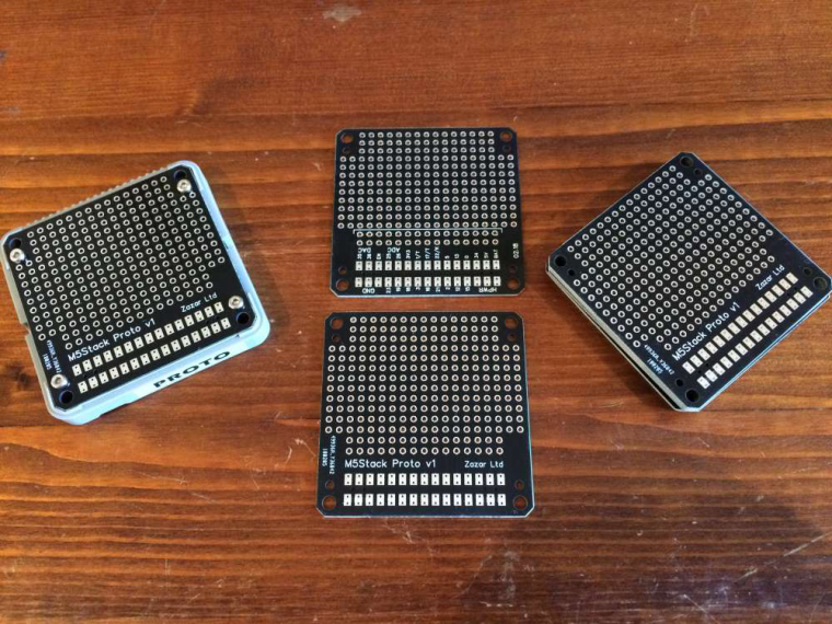
I ordered the M5Stack Proto board along with the core unit hoping to develop a working prototype that could be shown to potential users. While the board is fine I quickly realised that you couldn't use the battery back cover since wiring for the through holes would need to be connected to the female header.
This was a shame as it would make demonstrations require another power source and would show the internals underneath. So I have created my own version based on the M5Stack Proto board which fits into the shell.
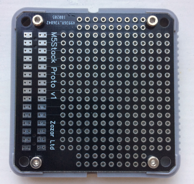
The header pads are connected to to first two rows of through holes allowing you to connect into the pins and replace the battery back cover.
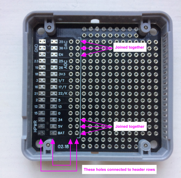
The pins follow the same vertical order but reversed horizontally i.e. the first header pads are connected to the second through hole. Both GND and HPWR pins are also connected and the holes tied together as with the header.
I have ordered a few sets of header pins from M5Stack which should arrive this week and then test to see if it works. The spacing of the tracks for the first header row are outside production tolerrance, however I will be only connecting a few pins at a time and it is for development purposes only.
-
nice, maybe more text Instructions on the board will be better.
-
Is the custom proto board working out good for you? I just received my stock Proto board and found the same limitation you did. I can’t connect any pins and use the bottom module. Do you have any extras for sale or where could I purchase it?
Also I noticed your ADC and DAC screen printed labels are swapped compared to the core. Is that a mistake or did you swap the pins in the design?
-
@m5stack 在 Custom Prototype Board 中说:
.
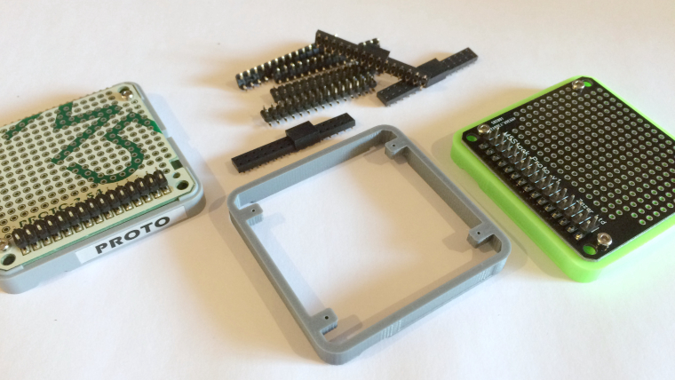
I've just received the headers, which seem to be custom parts so they're not readily available which is a shame (and expensive since they only ship them with a module or core). Once they have been soldered I'll test them and report back - thanks for the note on DAC/ADC it's a print error the pins are the same as the main board.I have also had a few blank enclosures made, with the holes removed, in both PLS and ABS for testing.
I really like the M5Stack but it's let down by not releasing more design files (for all the enclosure parts) and having better access to custom parts such as the headers so other developers can make their own modules.
-
@world101 the pins and the sockets are the customization. if u want more, u can order from me(email me), i will give u nice price. i had not swapped anything, it is the same.
-
Out of curiosity what package did you use to do your breakout boards? I am looking at drawing up a breakout sch/pcb in KiCad for sharing as we speak.
-
I used Easy EDA which imported the pcbdoc file after some messing around with the format. I will make the gerber and pcb files files available as well as the 3D prototype enclosure file (with solid edges) soon.
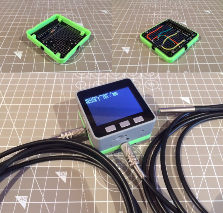
I have now tried out the new board with a couple of simple jack connectors and all seems to work!
-
@zazar Nice design !!! Thanks for the details and the photos.... and for making the files available soon.
-
The PCB and 3D case design files can now be found on GitHub at https://github.com/zazardev/M5Stack-Proto
For those using EasyEDA see https://easyeda.com/suremicro
-
This is excellent. Looks like you are doing a temperature reading (thermistor/thermocouple) setup, which is what I have been working on. Are you using a voltage divider to calculate temperature? If so, please provide your schematic.
Also, can you provide part numbers for the input jacks (2.5mm I assume)? I have some panel mount jacks that were for another case enclosure, but they are too big for the m5stack. Yours look great.
How accurate is the temperature? I've been reading the ESP32 ADC can be not quite linear and therefore not so accurate. So I was looking into another ADC breakout module like the ADS1115 for more resolution bits and accuracy.
-
Yes the device will be used to record multiple temperatures using DS18B20 sensors on one wire with a single 4.7k resistor. I hooked up 5 and can read them indiviudally since they have there own addresses. I only need the temperature to the nearest degree so they are fine for my purposes.
I actually use a 3.5mm jack and bought a few connectors as like you found that many do not fit, however the very small SMD mounted ones just fit in the standard case. The ones I found are on Amazon:
https://www.amazon.co.uk/dp/B008SO0E60/ref=pe_3187911_189395841_TE_3p_dp_1
-
Hello, your prototype board is very usefull, more than the genuine one.
It's possible to order a set from EasyEDA ?
-
Yes, if you head over to https://easyeda.com/suremicro the design is there which you can use to get your own boards made. I used JLCPCB.
-
@suremicro 在 Custom Prototype Board 中说:
Yes, if you head over to https://easyeda.com/zazarltd the design is there which you can use to get your own boards made. I used JLCPCB.
Haven't used JLCPCB, I've used Seeedstudio Fusion service https://www.seeedstudio.com/fusion_pcb.html a few times. They are especially good if you need several of the same board as they send 10 copies
-
@suremicro sorry its been a long time, but do you still have pcb/3D case somewhere ?
Gonna github / easyeda ... nothing found :( -
Hello! It looks like you're interested in this conversation, but you don't have an account yet.
Getting fed up of having to scroll through the same posts each visit? When you register for an account, you'll always come back to exactly where you were before, and choose to be notified of new replies (either via email, or push notification). You'll also be able to save bookmarks and upvote posts to show your appreciation to other community members.
With your input, this post could be even better 💗
Register Login