Let's start IoT with Ambient [English version]
-
Original full text forwarding http://pages.switch-science.com/letsiot/powermonitor/
Measure AC current value with M5Stack and clamp type current sensor
"Let's start IoT with Ambient" part 17, I measure the current value used by equipment using M5Stack and clamp type current sensor.
In homes, offices, factories and so on, so many devices are running with electricity. It is effective for energy conservation and cost reduction to measure the state of electricity usage of the equipment, to accumulate data and visualize it. In addition, it can be developed into watching services and services such as improving availability of facilities.
clamp type current sensor
The clamp type current sensor measures the current with the current flowing through the magnetic core. A magnetic flux is generated in the magnetic core by the current flowing through the electric wire, and a secondary current flows in the secondary winding accordingly. Connect a resistor there and measure the voltage across the resistor. Although this method can measure only AC, it is possible to measure the current without cutting the circuit to be measured by sandwiching the wire with the magnetic core divided into two.
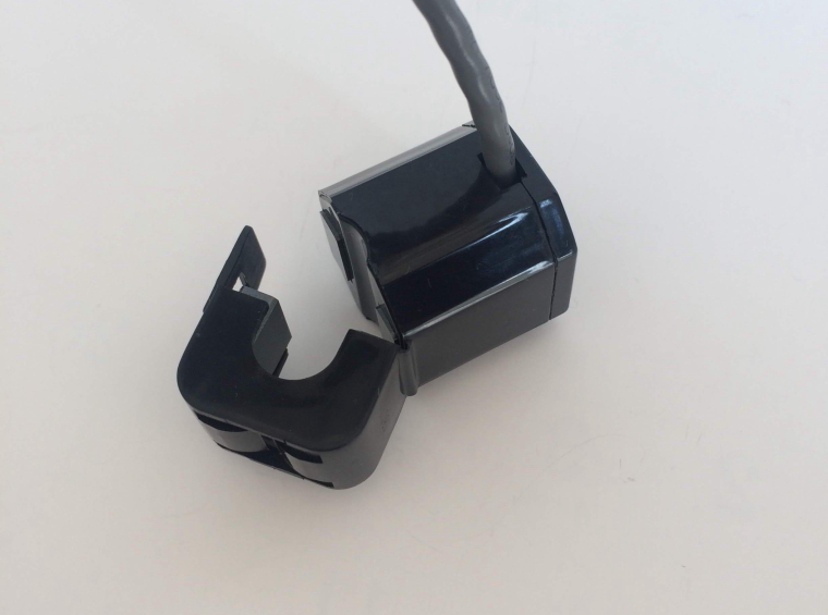
The sensor in the photo above is the "clamp type AC current sensor 30A" used this time. According to the data sheet, a secondary current of 2000: 1 is obtained for the current to be measured. If the current is 20 A, a secondary current of 10 mA will flow.
Measuring circuit
A circuit for measuring current using a clamp type current sensor is as follows.
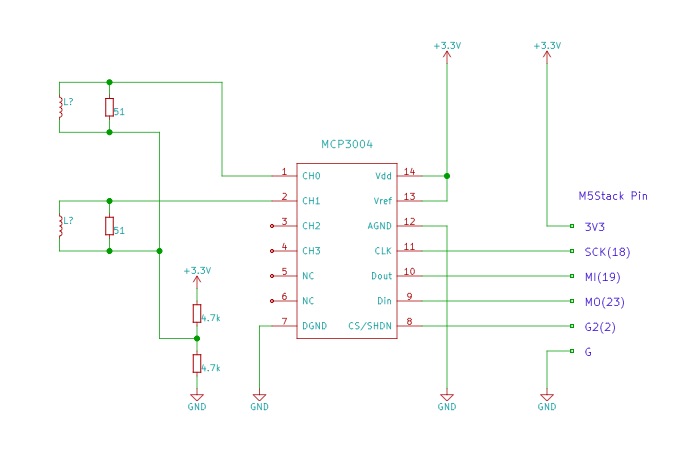
Connect a load resistor of 51 Ω to the secondary winding of the clamp type current sensor and measure the voltage at both ends with the AD converter MCP 3004. Since the AC is measured, the voltage across the load resistance is positive and negative. We made a half voltage (1.65 V) of the power supply voltage 3.3 V with two 4.7 kΩ resistors so that the voltage changes around 1.65 V as the center.
The MCP 3004 is a 10-bit AD converter and can read values from 0 to 1023 when the input is from 0 V to Vref V (= 3.3 V). Assuming that the value read by the AD converter is i, the voltage Vr across the load resistance is as follows.
Vr = (i - 512) / 1024 * 3.3
Since the load resistance is 51 Ω and the ratio of the primary current and the secondary current of the clamp type current sensor is 2000: 1, the primary current I can be calculated as follows.
I = Vr / 51 * 2000
It is a measuring circuit made on the bread board.
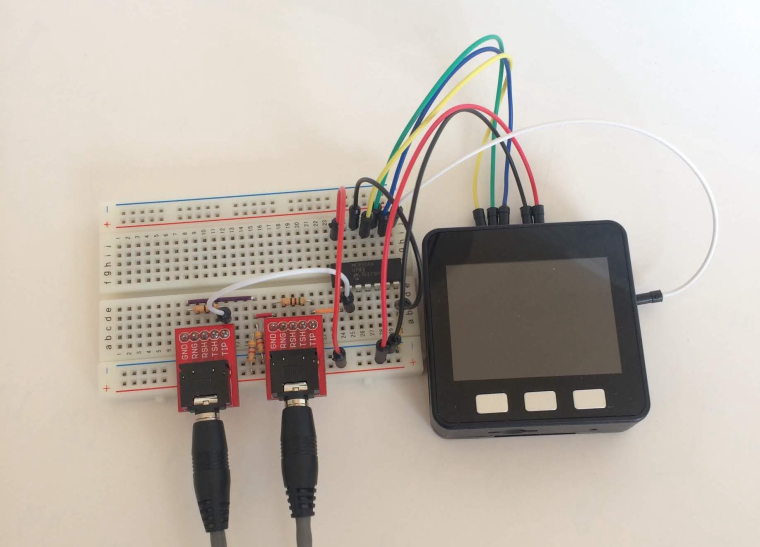
We gathered necessary parts for the sensor terminal.
part qty M5Stack Basic 1 Clamp type AC current sensor 30 A 2 Audio jack + pitch conversion board 2 Jumper wire (male to male) 1 Ordinary breadboard 1 MCP3004 1 Register(51ohm) 2 Register(4.7kohm) 2 Measure AC current
Electricity used in Japanese homes is 100 V interchange, East Japan 50 Hz, West Japan 60 Hz. In order to measure the AC current value, first measure the current value 100 times at 1 ms intervals. The process of periodically measuring the value is called sampling. Since 1 msec 100 times = 100 msec, 50 cycles are measured for 5 cycles, 60 Hz for 6 cycles.
The measurement program is as follows.
/*
 * M5Stack's current sensor test
 * Sampling 100 times every 1 ms with MCP 3004/3008
 * Sampling value and current value displayed serial terminal every 3 seconds
 * Confirm by serial plotter whether the value seems to be correct or noisy
 */
#include <M5Stack.h>
#include <SPI.h>
#include "MCP3004.h"

#define TIMER0 0

#define SAMPLE_PERIOD 1     // Sampling interval (msec)
#define SAMPLE_SIZE 100     // 1ms x 100 = 100ms

hw_timer_t * samplingTimer = NULL;

const int MCP3004_CS = 2;
MCP3004 mcp3004(MCP3004_CS);

const float rl = 51.0; // Load Resistance

struct amp {
    short amp_ch[4];
} amps[SAMPLE_SIZE];

volatile int t0flag;

void IRAM_ATTR onTimer0() {
    t0flag = 1;
}

// Sampling channels of ch

void ampRead(uint8_t ch) {
    timerAlarmEnable(samplingTimer);
    for (int i = 0; i < SAMPLE_SIZE; i++) {
        t0flag = 0;
        while (t0flag == 0) {
            delay(0);
        }
        amps[i].amp_ch[ch] = mcp3004.read(ch);
    }
    timerAlarmDisable(samplingTimer);
}

void setup(){
    M5.begin();

    Serial.begin(115200);
    while (!Serial);
    SPI.begin();

    mcp3004.begin();

    samplingTimer = timerBegin(TIMER0, 80, true);
    timerAttachInterrupt(samplingTimer, &onTimer0, true);
    timerAlarmWrite(samplingTimer, SAMPLE_PERIOD * 1000, true);
}

void loop() {
    ampRead(0);
    for (int i = 0; i < SAMPLE_SIZE; i++) {
        Serial.println(amps[i].amp_ch[0]);
    }
    delay(3000);
}

//curlog2.ino hosted with ❤ by GitHub
Prepare a timer that calls function onTimer 0 () at 1 ms intervals. Let's wait while the flag is 0 at the beginning of the for loop and set the flag to 1 with the function onTimer 0 () so that the for loop is executed at 1 msec intervals. By reading the AD Converter MCP 3004 in the for loop and storing the value in the buffer, the current value is measured at intervals of 1 ms.
The first program will print out the sampled data to see if the sampling of AC is working well.
The part accessing MCP 3004 is made into a library. We put the entire program including the library in Github.
Operation check
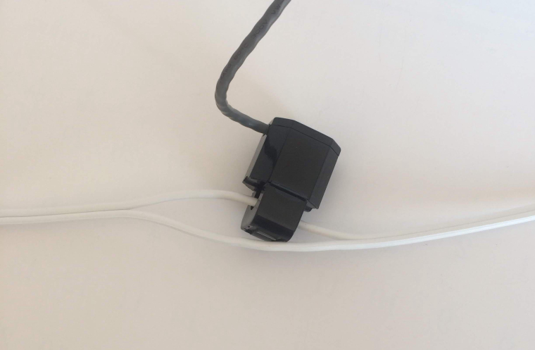
The power supply cable is made of two wires. Even if two wires are clamped, the current of the return and return is canceled, no magnetic flux is generated, and the secondary current does not flow. As shown in the photograph, we measure with just one of the two wires.
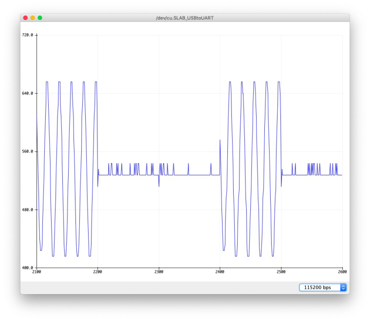
Build the program and transfer it to M5Stack and start the serial plotter instead of the usual serial monitor.
Connect the appropriate electrical products to the end of the power cable. In the experiment I connected a 1200 W dryer. When moving or stopping the dryer, the following waveform is drawn on the serial plotter. The waveform varies depending on the connected device, but it was confirmed that the AC waveform could be measured.
Find the AC current value
In order to find the current value of alternating current that fluctuates plus or minus, square the sampling value measured for several cycles to obtain the average value and take the square root.
The processing of that part will be as follows. The first program recorded all the values in the buffer to check the sampled value, but it is not necessary to calculate the current value. Every time sampling is done, squared sample values are added, and finally averaged to find the square root. If you call this process every minute, you can measure the current value every minute.
float ampRead(uint8_t ch) {
    int vt;
    float amp, ampsum;
    ampsum = 0;

    timerAlarmEnable(samplingTimer);
    for (int i = 0; i < SAMPLE_SIZE; i++) {
        t0flag = 0;
        while (t0flag == 0) {
            delay(0);
        }
        vt = mcp3004.read(ch);
        amp = (float)(vt - 512) / 1024.0 * 3.3 / rl * 2000.0;
        ampsum += amp * amp;
    }
    timerAlarmDisable(samplingTimer);

    return ((float)sqrt((double)(ampsum / SAMPLE_SIZE)));
}

//curlog2.ino hosted with ❤ by GitHub
AC power value
Power is voltage × current. Since the voltage of the household AC is 100 V, it does not become that it will become the power value if 100 V is multiplied to the current value.
Since there is a phase shift between the voltage and the current in the case of AC, the actual power (active power) used isActive power = voltage × current × power factor
I decided to grasp the tendency of electricity use by using the current value in order to investigate electricity usage pattern of equipment rather than obtaining accurate power value this time.
Display current value on LCD
Since the current value per minute is obtained, it is displayed on the LCD of M5Stack.
Prepare 100 ring buffers, store the current value every minute, and display the value in the ring buffer on the LCD. The program of the part displayed on the LCD is as follows.
// Ring buffer
#define NDATA 100
struct d {
    bool valid;
    float d1;
    float d2;
} data[NDATA];
int dataIndex = 0;

// Insert data into the ring buffer
void putData(float d1, float d2) {
    if (++dataIndex >= NDATA) {
        dataIndex = 0;
    }
    data[dataIndex].valid = true;
    data[dataIndex].d1 = d1;
    data[dataIndex].d2 = d2;
}

#define X0 10

// Calculate the y axis value from the data value
int data2y(float d, float minY, float maxY, int HEIGHT) {
    return HEIGHT - ((int)((d - minY) / (maxY - minY) * (float)HEIGHT) + 1);
}

// Read data from ring buffer and display it in graph
void drawChart() {
    int HEIGHT = M5.Lcd.height() - 10;
    float mind = 0.0, maxd = 10.0;
    for (int i = 0; i < NDATA; i++) {
        if (data[i].valid == false) continue;
        if (data[i].d1 > maxd) maxd = data[i].d1;
        if (data[i].d2 > maxd) maxd = data[i].d2;
    }
    maxd *= 1.1;
    for (int i = 0, j = dataIndex + 1; i < (NDATA - 1); i++, j++) {
        if (data[j % NDATA].valid == false) continue;
        int d10 = data2y(data[j % NDATA].d1, mind, maxd, HEIGHT);
        int d11 = data2y(data[(j + 1) % NDATA].d1, mind, maxd, HEIGHT);
        M5.Lcd.drawLine(i * 3 + X0, d10, (i + 1) * 3 + X0, d11, BLUE);
        int d20 = data2y(data[j % NDATA].d2, mind, maxd, HEIGHT);
        int d21 = data2y(data[(j + 1) % NDATA].d2, mind, maxd, HEIGHT);
        M5.Lcd.drawLine(i * 3 + 1 + X0, d20, (i + 1) * 3 + 1 + X0, d21, RED);
    }
}

void loop() {
    unsigned long t = millis();
    float a0, a1;
    a0 = ampRead(0);
    a1 = ampRead(1);

    putData(a0, a1);

    M5.Lcd.fillScreen(BLACK);
    drawChart();

    while ((millis() - t) < PERIOD * 1000) {
        delay(0);
    }

//curlog3.ino hosted with ❤ by GitHub
Please see Github for the whole program.
Send it to Ambient for visualization
Send current value per minute to Ambient for visualization.
Sending data to Ambient is easy. Connect to Wi-Fi with the setup function and initialize the Ambient object with ambient.begin (). Measure the current value in the loop function, set the data with ambient.set (), and send it to ambient.send ().
The program involved in sending to Ambient is as follows.
void setup(){
    // Various initialization

    WiFi.begin(ssid, password);
    while (WiFi.status() != WL_CONNECTED) {
      delay(500);
      Serial.print(".");
    }

    ambient.begin(channelId, writeKey, &client); // Initialize Ambient by specifying channel ID and write key
}

void loop() {
    unsigned long t = millis();
    float a0, a1;
    a0 = ampRead(0);
    a1 = ampRead(1);

    ambient.set(1, a0);
    ambient.set(2, a1);
    ambient.send();

  while ((millis() - t) < PERIOD * 1000) {
        delay(0);
    }

//curlog3.ino hosted with ❤ by GitHub
Please see Github for the whole program.
Measure the current consumption of the household
Many families in Japan are supplied with electricity in two systems called single phase three wire system. By measuring the current values of both of the two systems, we can measure the current use condition of the whole house.
It is a state that a clamp type current sensor is actually attached to the distribution board.
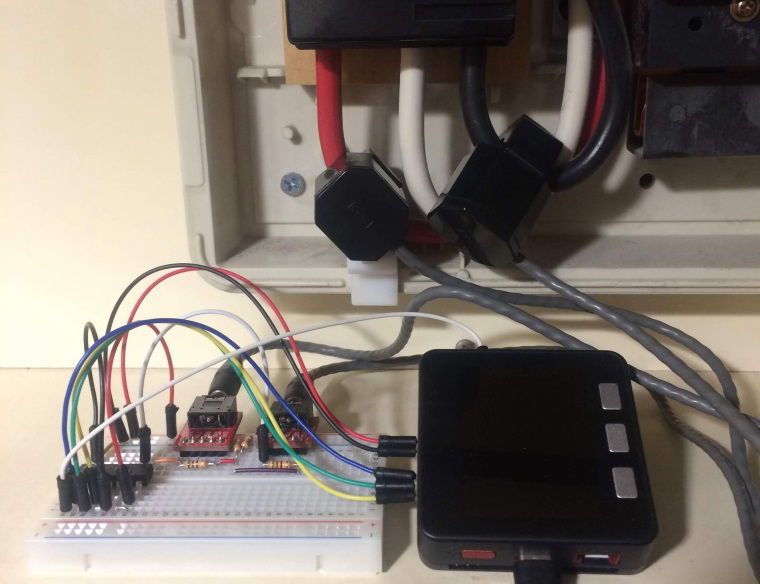
Please attach with care with the circuit breaker being dropped.
Looking at the measured current value with Ambient, the following graph is seen.
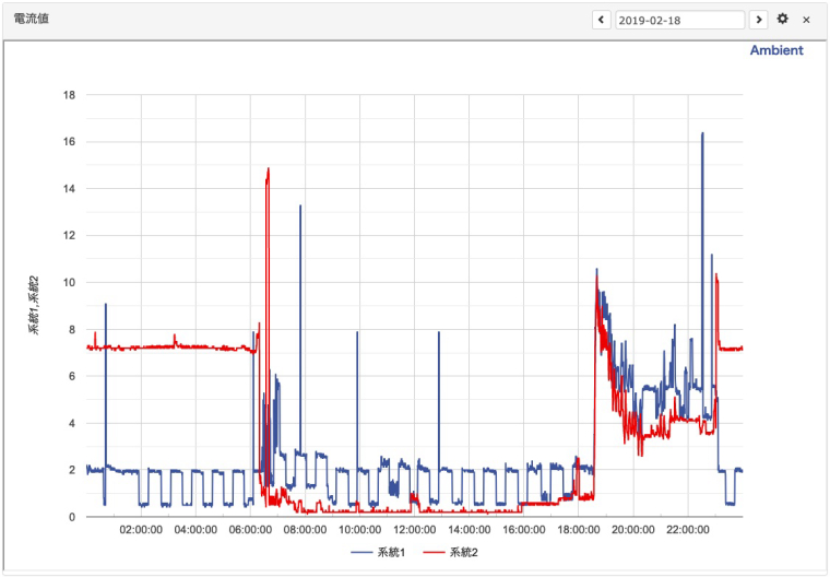
In the chart setting, set the graph size to "large", d1 and d2 are displayed in the same chart, and date specification is set.
The graph is the current value of the author's home. It is understood that the refrigerator is connected to line 1 (blue line), and it is constantly moving while repeating on / off. Line 2 has an oil heater and it runs from 0 o'clock to 6 o'clock. A big peak around 6:30 is an oven range.
Use prototype for M5Stack
M5Stack has "proto module" which can develop original extension module. We created a circuit that was confirmed with bread board using proto module. We made it possible to connect up to 4 current sensors.
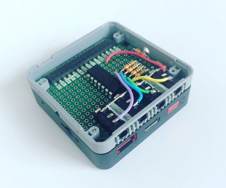
M5Stack can be expanded with extension module such as GPS module, but with proto module, it can also expand its own functions, further expanding its application range.
Summary
If the ammeter is installed at home, it will be possible to visualize the use situation of electricity at home and energy conservation awareness will be enhanced. If you examine the everyday trends, it seems that it can be used as watching service data.
If you look at the electricity usage status of machine tools in the factory, it will be possible to visualize the operating status of the machine and use it for improving the operation rate.
This article was written by Shimojima of ambient data.
Disclaimer
Although the article actually wrote after experimenting, it does not guarantee the operation. Switch science and ambient data are not responsible for any damage caused by using this article.
Hello! It looks like you're interested in this conversation, but you don't have an account yet.
Getting fed up of having to scroll through the same posts each visit? When you register for an account, you'll always come back to exactly where you were before, and choose to be notified of new replies (either via email, or push notification). You'll also be able to save bookmarks and upvote posts to show your appreciation to other community members.
With your input, this post could be even better 💗
Register Login