M5Stack with MIT App Inventor - Easy mobile app creation for your M5Stack
-
This tutorial assumes that you have already pre-installed the necessary com port driver, have installed the Arduino IDE (arduino.cc) m5stack board manager files and the m5stack library.
If you haven’t see the Arduino quick start guide on our docs page:
https://docs.m5stack.com/#/en/quick_start/m5core/m5stack_core_quick_startFirst of all why would we want to use MIT app inventor with M5Stack? MIT app inventor is a fantastic and simple tool that uses block programming and a simple UI to design android apps. You can download the .apk file for the app that you have designed and even publish it on the google play store.
Although UI flow already offers a remote mobile app function it is not robust enough yet to accommodate an app with a more sophisticated UI and also it is only accessible by scanning a QR code which connects to a webpage.
Currently I have only managed to use Arduino code to program the M5stack to work with MIT app inventor, but I am sure there will be a way to program this functionality soon with UI flow, especially now that the custom blocks function has now been integrated.
For the people out there who prefer to use blocks though do not fear. A computer science teacher from Tunisia by the name of Adel Kassah has developed a nice website (easycoding.tn A.K.A Tuniot) which allows the user to generate Arduino code for ESP32 by using blocks, and he has many nice tutorials on his youtube channel on how to use it.
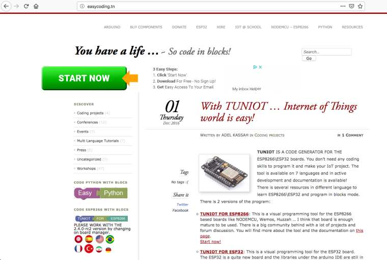
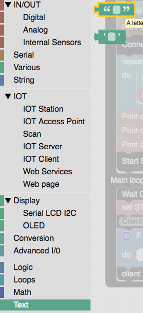
Let’s get started. First go to the website easycoding.tn scroll down the page until you see the icon
TUNIOT FOR ESP32 on the left side column. (!!Make sure you choose esp32 and not esp8266!!)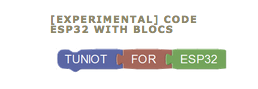
After you clicked the icon you will be greeted with the block interface that looks like this.
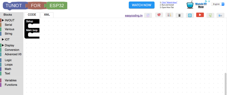
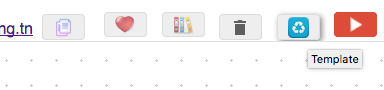
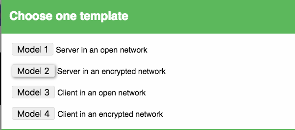
I will not go into detail on how this interface works as Adel already does a good enough job of that in his videos. He has created a bunch of templates for setting up a web server on your ESP32 device so we will choose one of those templates from the drop down templates panel which is called “server in an encrypted network”
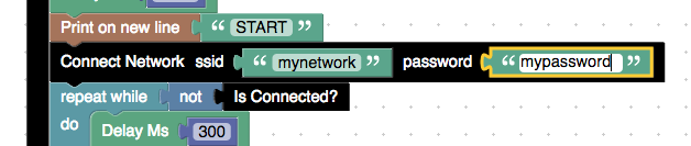
We need to first enter our wifi network and password into the black block labelled “Connect Network ssid “ ” password “ “ ” so we can connect our device to the network. (note: if you do not feel secure entering your home wifi details into this website it’s ok we can enter it offline in the arduino code later)
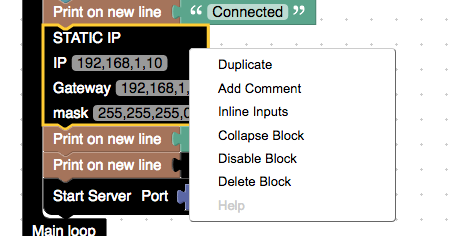
We also need to remove the block that assigns a static IP. Do this by right clicking the block and selecting delete block.
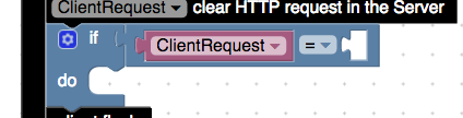
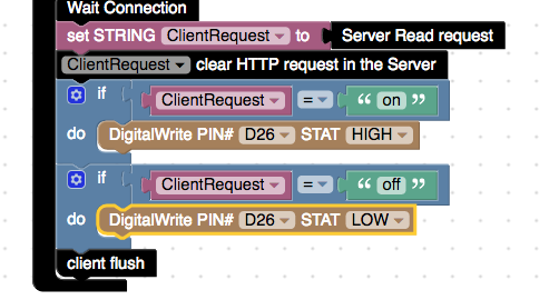
Next we need to get the clear http request block from the String section. In a moment we will be creating two if blocks which will compare the request against the string “on” or “off”. This clear http request block will remove any unnecessary data from the http request in order to compare the strings better ( if we don’t use this block our http request will look like this “GET /on HTTP/1.1)
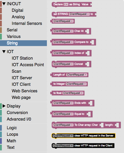
Add this block in below the set STRING client request to server request block.
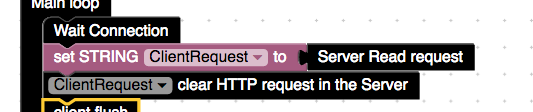
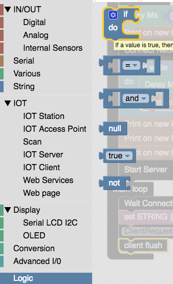
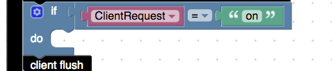
Now we can set the two if blocks for off and on http request. We get the if block and comparator block the first two blocks from the logic section and drag them in above the client flush block.
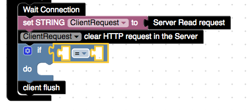
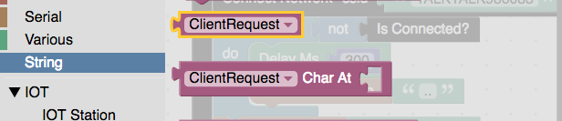
Now we get the client request block from the string section and place it in the first empty slot in the logic block we just placed.
Next we need to go into the text section to get a blank block with quotation marks around it, this block creates a string which we can type something into such as “on” and then compare whether the http request has the same message or not.
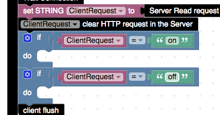
Duplicate the last steps to create an if condition for off as well.
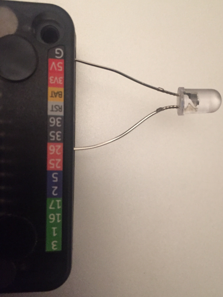
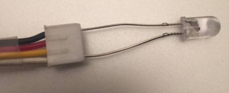
Now for this simple example we will light up an LED on pin 26 which is easy to find on the base of the core, but for go and fire users you will have to insert a grove connector into port b (black port) and stick the LED into the end of the grove cable connector. Attach the short leg of the LED which is ground into the left side of the connector which has a black wire connected to it and the other leg into the right side which has a yellow wire connected to it.
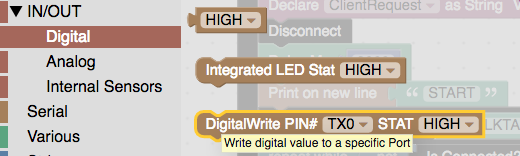
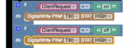
To finish off the code on this website we find the digital write pin block in the digital section of IN/OUT and place one in each of the if conditions we just made.
Then change their values to these
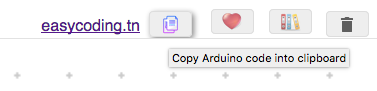
Now were done with the blocks code on this site, click on the copy arduino code to clipboard code button, load up the arduino IDE, create a new sketch and paste the code in.
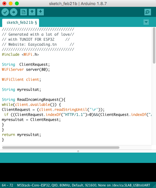
Now make sure your m5stack is plugged in and port and correct m5 stack board is selected. Although this code will work fine theres some small adjustments we can do to make our lives easier. Unless we do a scan of devices on our network we don’t know what the IP dress of our M5stack device is. So before we upload this code we can make some minor adjustments to display the IP address on the screen of our device.
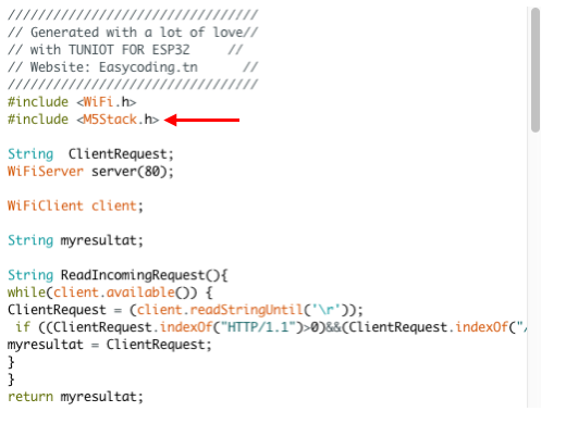
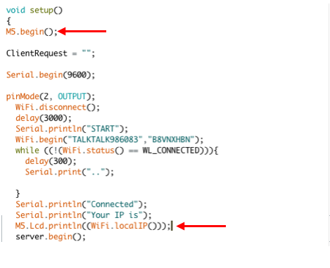
At the very top of the sketch below #include <Wifi.h> we can add the line #include <M5Stack.h> to include the m5stack library.
Now let’s scroll down to the void setup() section and add this line which initializes the m5stack M5.begin
and replace the line Serial.println((WiFi.localIP())); with M5.Lcd.println((WiFi.localIP()));
Now we can test that this works before we create the app. Upload the code to your device wait for it to display its IP address on the screen which should look something like 192.168.x.x.
Copy that IP address into the browser and then add a forward slash followed by on like so:
http://192.168.1.8/on if you did everything correctly your LED should now turn on, to turn it off simply replace on with off in the http request http://192.168.1.8/offNow to design the app we need to go to http://ai2.appinventor.mit.edu
To test the app we will need to install the app inventor companion app on our android device. You can search for it on the google play store and install it from there. Or if you cannot access the play store the app inventor website has provided an .apk link (http://ai2.appinventor.mit.edu/companions/MITAI2Companion.apk) which you can copy via bluetooth or sd card to your android device and install from the file explorer.
If you do not have an android device or need more information on how to get setup you can follow this link http://appinventor.mit.edu/explore/ai2/setup.html
Create the App
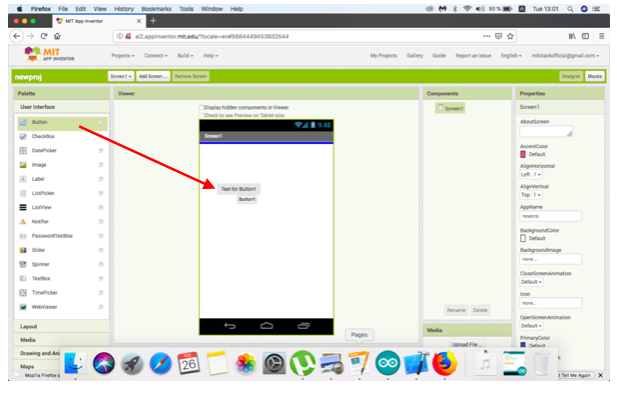
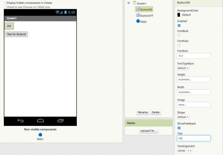
Once your setup with the app or emulator start a new project and drag two buttons from the pallete to the screen.
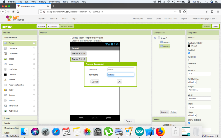
After dragging the two buttons to the screen we can rename them from button 1, button 2 to something more descriptive like ButtonON, ButtonOFF. Select the the button in the components section and click on the rename button below.
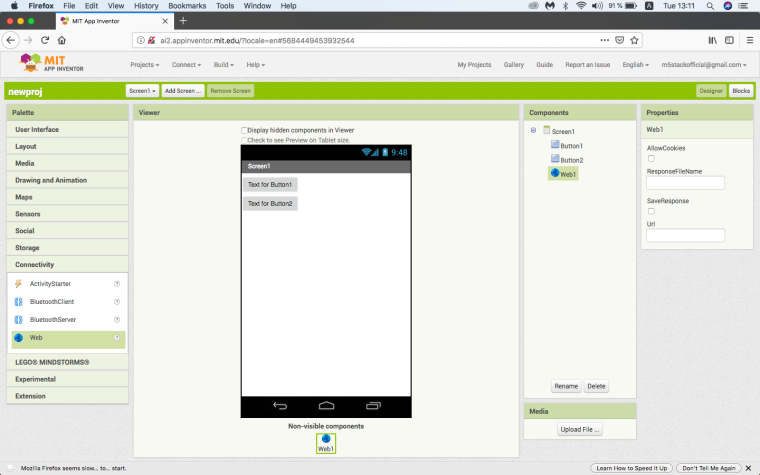
Aside from the two buttons we also need to drag a web component from the connectivity tab of the palette on to the screen. No icon will appear on the screen for the web component but we can tell that it has been added as it will appear in the components section.
Change the text of your buttons by selecting them in the components section and editing them in the text field of the properties section.
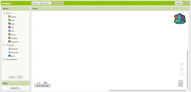
That’s all for the layout, let’s move to the blocks to complete the app. Press the blocks button in the top right hand corner of the window to move to the blocks page. This is where we will write the code for our app.
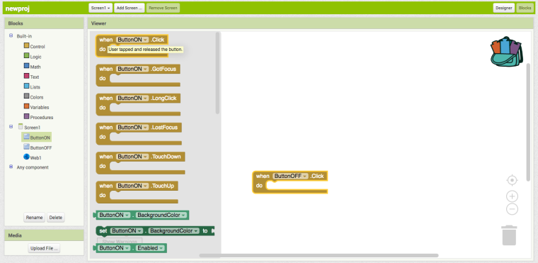
First we will need to grab two button click blocks from the button section in the blocks menu, click the drop down list to change them to ButtonON and ButtonOFF like so.
Enter the web section and drag the “set web1 url to” blocks into the button click blocks
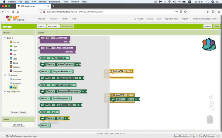
Now this is how we send the http request with the app. Take an empty text block from the Text section of the blocks menu and place it in the slot at the end of the set web1 blocks we just placed. Now we need to enter in the url that we just typed in our browser to turn the light on or off into the text blocks we just placed.
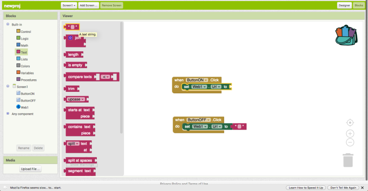
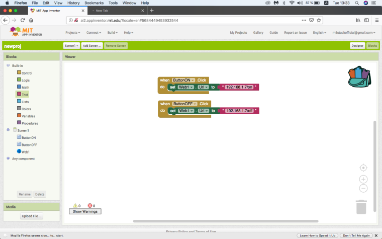
The result should look something like the following image. Remember the IP address of your device will be different to mine, so remember to double check that the IP address on the screen of your M5 is the same as what you entered in the block.
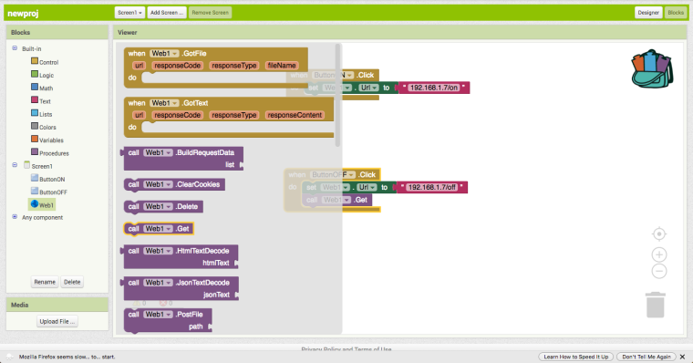
Lastly we need to add the “call web1 .get” blocks from the web blocks and add them below the http request.
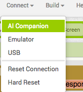
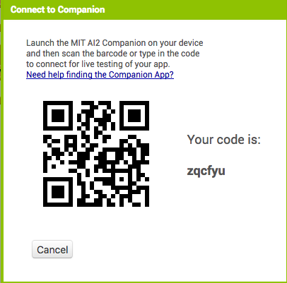
Now our app is finished and we can test it by clicking on connect choosing the ai companion option and scan the qr code.
Hope you enjoyed this tutorial. Show us what M5 apps you create.
-
This post is deleted!
Hello! It looks like you're interested in this conversation, but you don't have an account yet.
Getting fed up of having to scroll through the same posts each visit? When you register for an account, you'll always come back to exactly where you were before, and choose to be notified of new replies (either via email, or push notification). You'll also be able to save bookmarks and upvote posts to show your appreciation to other community members.
With your input, this post could be even better 💗
Register Login