How many of the M-Bus GPIO capable of capacitive input (TOUCHx) ?


-
Hi everyone, I'm about to get my first M5Stack, and for the main use I have for it I'd need capacitive inputs, or at least 3 of the 10 available on the esp32.
In the image below (from the esp32 datasheet), you can see there are 10 GPIOs capable of getting capacitive input, named from TOUCH0 to TOUCH9.
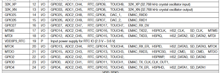
Looking at the schematics, it seems that a good part of this inputs are already dedicated to some other function, namely- GPIO32
- GPIO33
- GPIO27
- GPIO14
for the LCD display - GPIO4
for the SD card.
The remaining GPIOs available are 0,2,12,13,15; and they are all marked as "IO" as alternative function in the M-Bus definition of the schematic (see below)
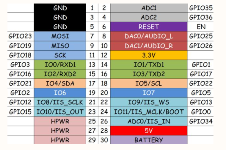
Of these, only GPIO0 seems to be dedicated to some hardwired function (Auto-Download), while also having a pullup resistor, while the rest of them don't seem to be bound to anything.
Can anybody confirm if the only available pins for touch input are 2,12,13,15 (and possibly 0) ? Or, are they also unavailable for some other reason?
Thanks everyone for your time!
-
G2 and G12 In the ESP32 boot process. have voltage level requirements. so you can't use they. otherwise it will affect the ESP32 boot
-
Thanks for the reply. However, could they be used as this kind of input afterwards? Like, plugging the electrodes in after the booting has completed?
Also, is 0 definitely unavailable for this purpose? -
@brus after boot you can use the G2 ,G12. the G0 if you don't need download program operation you can use it
-
Thanks! That's perfect, cause I need at least 3 of them for an usable application, and 5 would be ideal. I wonder, would it make sense (to your knowledge) to decouple G2 and G12 from the electrodes at boot time, by placing a MOSFET inbetween the connections, which in turn would be activated at runtime from another GPIO of the M-Bus, acting as output? In this way it wouldn't be necessary to physically disconnect the electrodes every time.
-
Use the M5Stack with the makey 16-channel capacitive touch unit !
I've made a banana touch keyboard using the M5Stack and the makey hub as shown with the original Arduino-MakeyMakey in https://www.youtube.com/watch?v=pfjWdoW7pt4 .You can program the makey banana keyboard using blockly.
good luck crami25
Hello! It looks like you're interested in this conversation, but you don't have an account yet.
Getting fed up of having to scroll through the same posts each visit? When you register for an account, you'll always come back to exactly where you were before, and choose to be notified of new replies (either via email, or push notification). You'll also be able to save bookmarks and upvote posts to show your appreciation to other community members.
With your input, this post could be even better 💗
Register Login