Sim800l
-
Re: Sim800l module
I can't seem to find any documentation on the use of this module. Can you please provide an example file showing the supported AT commands. Also I can't find any information on the pinout for this board. From a users perspective it really is unfortunate to buy a product and struggle to figure how to use it. The m5stack, up to this point, was a terrific experience because you guys had samples and drawings and solid documentation. In the future I suggest only releasing modules once they are fully documented. -
@jpilarski Hi Jp,
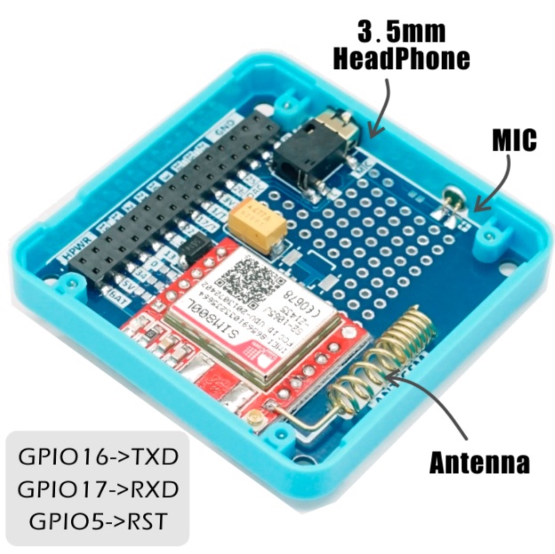
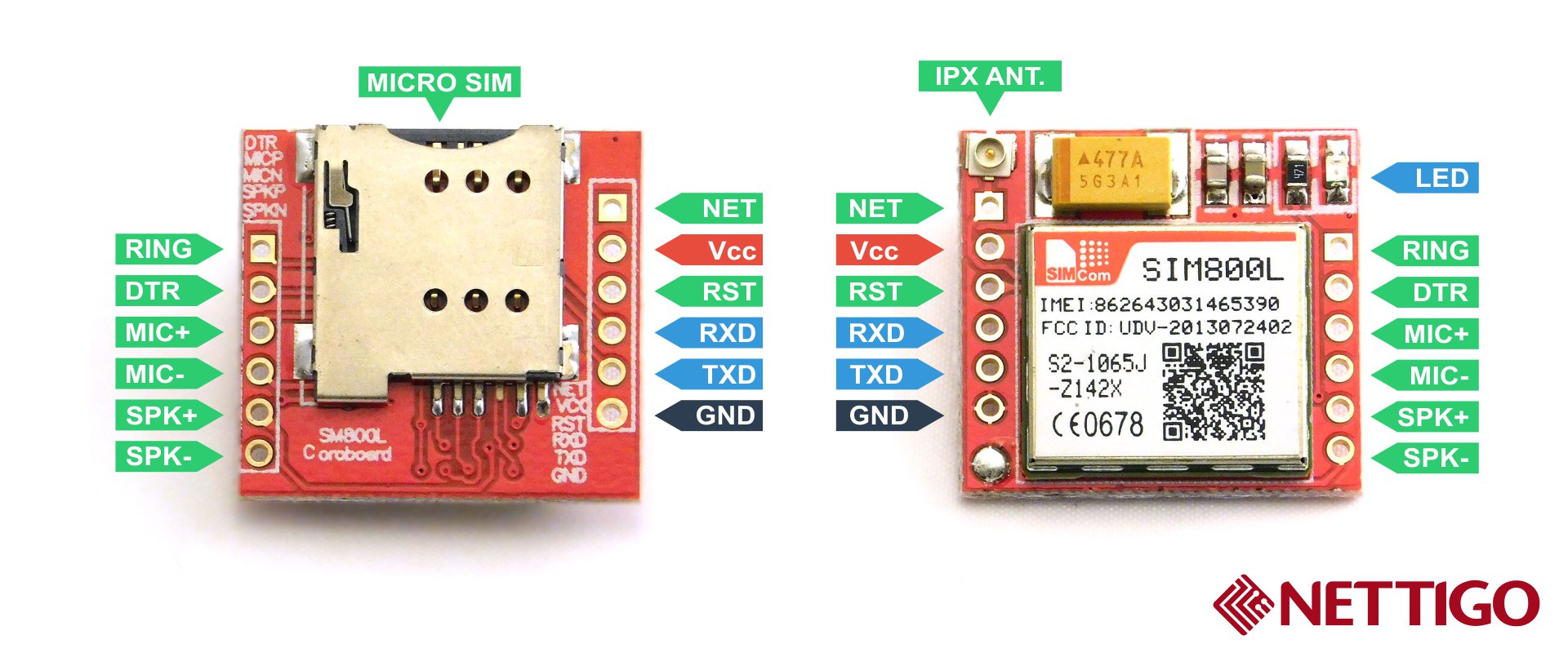
Not sure where you purchased yours but they should have included the photo below outlining the pin-outs used.
Here is a link to a manual for the AT command set for this sim module:
https://cdn-shop.adafruit.com/datasheets/sim800_series_at_command_manual_v1.01.pdfThere are many more datasheets at the Simcom website link if you are prepared to register:
http://simcomm2m.com/En/module/detail.aspx?id=138Here is a link to a simple program that could form the basis for use with the M5 stack.... You can probably find more examples on github.
http://www.ayomaonline.com/programming/quickstart-sim800-sim800l-with-arduino/It will need some conversion to make it compatible with the M5Stack. For starters you would need to add this to the start:
#include <M5Stack.h>
The GSM format used on this module is not supported in my country so I have no experience using it.
Good luck.
-
If you can Russian the best manual for SIM800L here
http://codius.ru/articles/GSM_модуль_SIM800L_часть_1
Many sketches for Arduino that can be easily conversion to M5 Stask.
Just replace
#include <SoftwareSerial.h>
SoftwareSerial SIM800 (8, 9); // 8 - RX Arduino (TX SIM800L), 9 - TX Arduino (RX SIM800L)
toHardwareSerial SIM800 (2); // pin 16 = RX, pin 17 = TX
for example
https://yadi.sk/d/SxWs6t0x3UBco6 -
Thanks very much. Is the mic on GPIO5. I was just making a purchase on amazon and thought I'd try out a module. This image wasn't on the re-sellers page. I wasn't even sure what it did and figured it would be a new thing to learn about. Really your documentation has been really great. It makes a huge difference to users. The enjoyable experience of using your product is what made me want to purchase a module. Maybe there should be a page for each module with all the relevant information just in case the re-seller isn't providing it.
-
@jpilarski 在 Sim800l 中说:
Is the mic on GPIO5
No. mic and headphone are connected direct to SIM800L module.
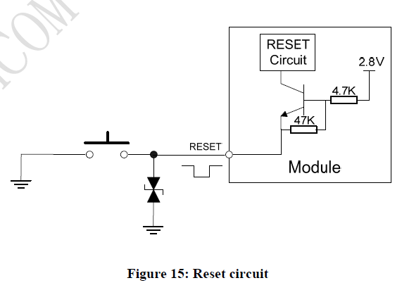
GPIO5 is reset.
Interconnection
M5 Stask <> SIM800L
Vbat - Vcc (3.7-4.3V)
GPIO16(RX) - TXD
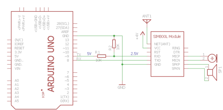
GPIO17(TX) - RXD (must be not direct 3.3V > 2.5V)
GPIO5 - RST
GND - GNDRING is not used.
DTR is not used.MIC+, MIC- to microphone.
SPK+, SPK- to headphone.Example for Arduino
-
Hello
any update of demonstration source code for the sim module with realtime streaming audio over Gsm ?
Looking for using it as a basic talking only smartphone in full duplex, send and receive at the same time ?
If possible Under Arduino IDE , with ino file ...
Good project and information..
...
Great day.
Jp -
if it can help you :
http://miliohm.com/sim800l-arduino-tutorial/Br
Jp -
Just found an important fact that's mentioned nowhere: there are 2 ways to insert the SIM Card (uhm, maybe four …). Note that one corner is cut off. This does NOT go in first. When you put in the SIM Card, it will look towards your right hand.
Now the AT commands work ...
-
#include <M5Stack.h>
HardwareSerial Serial2(2);
void setup() {
M5.begin();
M5.Lcd.printf("GSM Test"); // just to see that the program has started
Serial.begin(115200); // switch on the serial "terminal" of Arduino IDE// Serial2.begin(unsigned long baud, uint32_t config, int8_t rxPin, int8_t txPin, bool invert)
Serial2.begin(9600, SERIAL_8N1, 16, 17); // 9600 baud seems to be the default for modems; pins as printed on the PCB board
at("", 200);
at("Z", 200); // reset all parameters to the user defined profile
at("I", 200); // display product info
at("+CPIN?", 200); // unlocked ?
at("+CGREG?", 200); // check the registration status of the device
at("+COPS?", 2000); // get operator
at("+CSQ", 200); // check signal quality
at("+CNUM?", 200); // find phone number of the device
at("+CNUM", 2000); // find phone number of the device
at("+ATS0=3", 200); // answer incoming calls after 1 ring tone(s)
at("+CREG=1", 200);
at("+CREG?", 200);
at("+CFUN=?", 200); // list functionality levels
at("+CFUN=1", 200); // set to full functionality
// at("+COPS=1,0,"E-Plus"", 200);
at("+CR=?", 200); // service reporting control
at("+CGATT=?", 200);
at("+CGATT=1", 200);
Serial2.printf("AT+CSTT="%s","%s","%s"\r\n", apn, user, pass);
delay(200);
Serial.print(Serial2.readString());
at("+ICCID", 200);
at("+GSN", 200);
at("+CIICR", 200);
at("+CIFSR", 200);
at("+CPOL?", 200);
at("+COPS=?", 2000); // get operators
}void at(char* sCmd, unsigned long lDelay) {
Serial2.printf("AT%s\r\n", sCmd);
delay(lDelay);
Serial.print(Serial2.readString());
}// now that the intro is done, we go into an interactive loop, where we can enter AT commands or press a button to do something
void loop() {if(Serial.available()) {
int ch = Serial.read();
Serial2.write(ch);
M5.Lcd.write(ch);
}if(Serial2.available()) {
int ch = Serial2.read();
Serial.write(ch);
}
if (M5.BtnA.wasPressed()) {
M5.Lcd.printf("\nhangup");
at("H", 200); // hangup
}
if (M5.BtnB.wasPressed()) {
M5.Lcd.printf("\ndialing");
at("L8", 200); // volume 0-9
at("D0043xxxxxxxx;", 2000); // dial
}
if (M5.BtnC.wasPressed()) {
M5.Lcd.printf("\nsms");
at("+CMGF=1", 200); // set the GSM Module to text mode
at("+CMGS="+43xxxxxxxxxx"\rTest SMS by Walter\x1A", 2000); // sms
}
M5.update();
} -
the code above works with my SIM800L module.
not all is necessary, but maybe helpful …
what I have learned up to now:
-
it works with HardwareSerial; no libraries to declare; default pins
-
I can make phone calls
-
I can send and receive SMS
-
the audio of the phone is not connected to the M5Stack; it's just the bare minimum.
-
if required, I might connect a better antenna - there is a connector on the SIM800L module and a hole in the base module I could use.
-
no soldering, no cables, no voltage problems
-
no EDGE, no LTE
-
the LED on the SIM800L module can be seen through the headphone hole.
-
the Arduino IDE installation brings a GSM library, but it is not listed under examples in the IDE.
bye for now
Walter -
-
I suggest to use the TinyGSM library (tested and it works)
https://github.com/vshymanskyy/TinyGSM
in the example sketches simply change serial1 to serial2
:D
-
@wschnell Hi, sorry for the late response...;-)
I'm trying your code but Arduino doesn't compile with this error:
Compilation error: 's' was not declared in this scopeabout this line:
Serial2.printf("AT+CSTT="%s","%s","%s"\r\n", apn, user, pass);no way to work with SIM800L MODULE!!
tips??
-
Hello @cepics
try changing the line to:
Serial2.printf("AT+CSTT=\"%s\",\"%s\",\"%s\"\r\n", apn, user, pass);Thanks
Felix
Hello! It looks like you're interested in this conversation, but you don't have an account yet.
Getting fed up of having to scroll through the same posts each visit? When you register for an account, you'll always come back to exactly where you were before, and choose to be notified of new replies (either via email, or push notification). You'll also be able to save bookmarks and upvote posts to show your appreciation to other community members.
With your input, this post could be even better 💗
Register Login