Where did ADC go in V1.1.2?
-
With the new V1.1.2 firmware today, it seems that we've lost the ADC functions under the Advanced menu. I think it is causing issues with my flow.
I'm trying this simple flow with a non-contact water sensor (XKC-Y25-T12V).
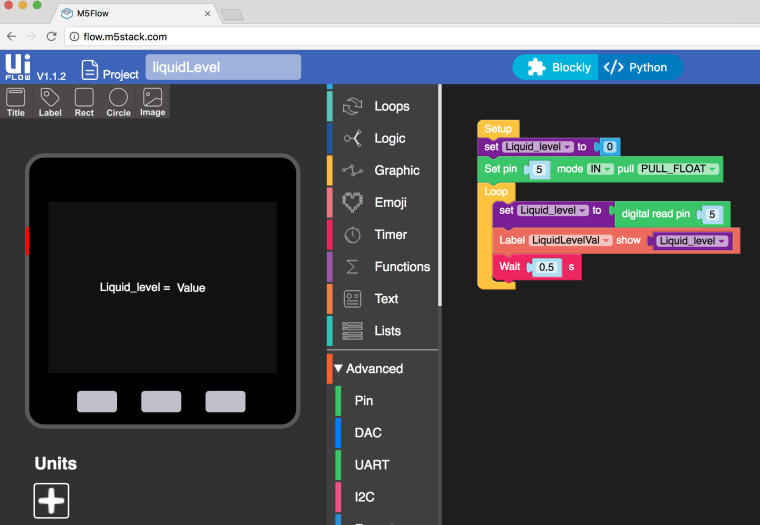
I could be doing something wrong, as this is my first attempt at creating a uiFlow from this Arduino example sketch:
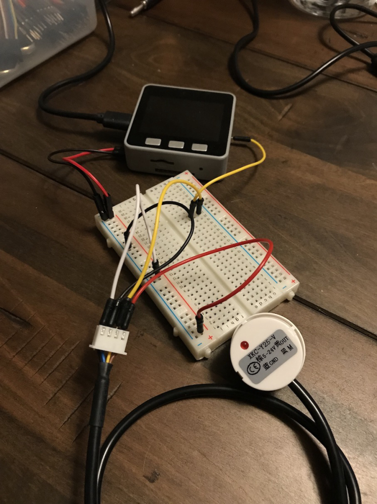
https://www.dfrobot.com/wiki/index.php/Non-contact_Liquid_Level_Sensor_XKC-Y25-T12V_SKU:_SEN0204I have VCC (brown) and GND (blue) connected between the water sensor and the m5stack. Then I have the OUT pin (yellow) of the water sensor connected to G5 (GPIO 5) of the m5stack (grey bottom). Finally, I have the ADJ pin (black) connected to GND. The sensor is working properly. I fill a glass of water about half way full. When placing the sensor on the side of the glass above the water, the LED on the sensor is off and the voltage reads 0V on my multimeter. When I slide the sensor down to below the water line, it detects the water, the LED on the sensor turns on, and the voltage reads about 4.75V on my multimeter.
Upon uploading to my m5stack grey core, I get this error:
AttribueError("type object 'ADC' has no attirbute 'OUT'",)Any ideas? I'm no sure if uiFlow has a bug or my program.
-
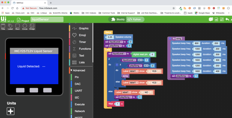
After some trial and error, I figured it out. A few changes I made:
- Removed the "Set pin" block. This allowed the flow to compile without error.
- Connected the ADJ pin (black) to VCC instead of GND per the sensor datasheet.
- Added an audible tone function to the flow so a song will play when the liquid is detected.
- Updates to the UI interface
I'm still not sure why the ADC causes an error when the Set pin block is inserted. @heybin or @watson, perhaps you can look into that.
-
All I can tell you is that ADC only works through the ADC pins on the base plate,
The Grove port on the Core and gray is a digital i2C port.
I'm still experimenting with a home-made rotation sensorUIFlow, so easy an adult can learn it!
If I don't know it, be patient!
I've ether not learned it or am too drunk to remember it!
Author of the WIP UIFlow Handbook!
M5Black, Go, Stick, Core2, and so much more it cant be fit in here! -
Here is a video: https://youtu.be/zWNDvSm6klk
-
@ajb2k3 said in Where did ADC go in V1.1.2?:
All I can tell you is that ADC only works through the ADC pins on the base plate,
The Grove port on the Core and gray is a digital i2C port.
I'm still experimenting with a home-made rotation sensorI'm using GPIO5 on the base (bottom) of the M5stack grey core. I haven't received my Grove cables yet, but once I do, I plan to test this on the M5stack fire as well.
-
@world101 The M5Go and M5 fire use Port B for analog sensors but don't have the I/O base that the Core and Gray have.
As a followup, the units will work on the core via the adc pins 35&36
-
I'm not looking to use the ADC blockly functionality in my flow above. The sensor I have can be considered a digital sensor. It only reports low (0V) or high (VCC) when capacitance is detected from a liquid. So I'm using digital pin functions within uiFlow.
I'm just pointing out the fact that uiFlow is missing a bunch of blockly functions that I think were there in v1.1.1, but are gone in v1.1.2. Looking at your manual I see these under the Advanced menu. The ones in bold are missing from v1.1.2 of uiFLow. This might be the cause of my errors with the Set pin blockly function I was using in my first post flow. Not sure???
Advanced,
Pin,
Analog Pin Write,
Analog Pin Read,
Digital Pin Read,
Digital Pin Write,
Set Pin Mode,
Map Pin,
GPIO,
Set Pin Out of Pin,
Set Pin In,
Set Pin Out,
Set Val to Pin In Value
PWM,
Set PWM of Pin,
Set PWM Frequency,
Set PWM Duty Cycle,
ADC,
Set ADC Pin to Value,
Set Item,
Set ADC Pin Bit Width,
Read ADC Pin,
DAC,
Set Dac,
Write Value to Dac,
UART,
Set Uart,
Read Uart,
Read Uart (0) Characters,
Read a Line of Uart,
Read Uart and Write to Buffer,
Read Uart Status?,
Write Value to Uart,
I2C,
Set I2C in Port,
I2C Scan Available,
I2C Address (0) is Ready,
I2C Read Address (0) count (0),
I2C Read Address (0) Reg (0) Count (0),
I2C Read Address (0) One Byte,
I2C Read Address (0) Reg (0) One Byte,
Execute,
Execute Code,
Network,
WIFI Connect,
MQTT,
MQTT Setup,
MQTT Subscribe,
MQTT Start,
Get Topic Data,
Publish Topic, -
Thank you for checking out my handbook, I'm glad to see that is proving useful so far.
And thank you for pointing out the missing code blocks.Out of curiosity can you share any pics and information on your sensors?
0 or 1 values from a water sensor?
(don't shout at me because I know you said not blocky, however,)
According to the M5 Documentation, the Earth Sensor Unit is a water sensor that has a variable input and outputs both analog and digital values.
Would you mind testing the earth sensor blocks on your sensor and let me know the outcome for my handbook please?Ok back to the subject of alternative code use, again using the earth sensor,
in mycropython you can tryfrom m5stack import * from m5ui import * import units clear_bg(0x111111) adc0 = units.get(units.adc,units.PORTA) earth0 = units.Earth(units.PORTA) btnA = M5Button(name="ButtonA", text="ButtonA", visibility=False) btnB = M5Button(name="ButtonB", text="ButtonB", visibility=False) btnC = M5Button(name="ButtonC", text="ButtonC", visibility=False) label0 = M5TextBox(136, 127, "Text", lcd.FONT_Default, 0xFFFFFF) while True: label0.setText(str(earth0.a_read())) wait(0.001)or
from m5stack import *
from m5ui import *
import units

clear_bg(0x111111)
adc0 = units.get(units.adc,units.PORTA)
earth0 = units.Earth(units.PORTA)


btnA = M5Button(name="ButtonA", text="ButtonA", visibility=False)
btnB = M5Button(name="ButtonB", text="ButtonB", visibility=False)
btnC = M5Button(name="ButtonC", text="ButtonC", visibility=False)
label0 = M5TextBox(136, 127, "Text", lcd.FONT_Default, 0xFFFFFF)


while True:
  label0.setText(str(earth0.d_read()))
  wait(0.001)
Please can you try this and let me know the outcome please?
-
I would try your tests, but unfortunately, I don't have the Earth sensor from M5stack. I have a few things on order (Relay unit, hexagon neopixel unit, etc.), but the Earth unit is not one of them. I only have the water sensor I linked in my first post, model XKC-Y25-V. It's not from m5stack. Here is a link to a better datasheet.
http://www.naylampmechatronics.com/img/cms/Datasheets/XKC Y25 T12V.pdf
I just wire it straight to my m5stack core using jumper wires. The yellow wire goes to GPIO5 on the bottom of my m5stack grey.
-
Apparently those blocks have now all been moved into the pin section, you can set the pwm duty within the analog write block and there is a block for setting a pin to in or out etc.. I cant see the adc bit width equivalent block anywhere. As i'm not too familiar with the functions of those blocks I never used them so please let me know if these reassigned blocks give the same function or not.
-
@world101 Ah, sorry for the misunderstanding, I don't mean test the actual earth sensor, I mean can you test the code with your sensor, please?
UIFlow, so easy an adult can learn it!
If I don't know it, be patient!
I've ether not learned it or am too drunk to remember it!
Author of the WIP UIFlow Handbook!
M5Black, Go, Stick, Core2, and so much more it cant be fit in here! -
@lukasmaximus said in Where did ADC go in V1.1.2?:
Apparently those blocks have now all been moved into the pin section, you can set the pwm duty within the analog write block and there is a block for setting a pin to in or out etc.. I cant see the adc bit width equivalent block anywhere. As i'm not too familiar with the functions of those blocks I never used them so please let me know if these reassigned blocks give the same function or not.
The Set pin block seems to cause the issue I was seeing with "AttribueError("type object 'ADC' has no attirbute 'OUT'",)". Now that I removed it, the flow is working fine. You are correct though, it looks like the Pin menu (presumably for GPIO pin functions) now has the combined blocks from Pin and ADC, but missing some blocks like ADC bit width, as you said. I wonder if that is on purpose. The Unit ADC from m5stack has the ADS1100 chip that supports up to 16 bits. Maybe the blockly code assumes users will only want to use 16 bits of resolution and not less???
-
@ajb2k3 said in Where did ADC go in V1.1.2?:
@world101 Ah, sorry for the misunderstanding, I don't mean test the actual earth sensor, I mean can you test the code with your sensor, please?
I tried to wire my breadboard jumpers to port A of the Fire, but they didn't fit too well (2.54mm vs. 2.00mm pin pitch). I will have to wait on my shipment of Grove cables from Aliexpress. Also, it looks like you have the ADC unit and the Earth unit both defined on port A. uiFlow didn't like that.
So instead of trying to use the Unit functionality within uiFlow, I wired up the m5stack Grey again and used the Micropython console. This code works with my liquid sensor:
from m5ui import *

clear_bg(0x111111)

pinin = machine.Pin(5, machine.Pin.IN)

btnA = M5Button(name="ButtonA", text="ButtonA", visibility=False)
btnB = M5Button(name="ButtonB", text="ButtonB", visibility=False)
btnC = M5Button(name="ButtonC", text="ButtonC", visibility=False)
label0 = M5TextBox(136, 127, "Text", lcd.FONT_Default, 0xFFFFFF)


while True:
    val = pinin.value()
    label0.setText(str(val))
    wait(0.1)
It reports a 0 (no liquid) or 1 (liquid detected) on the m5stack LCD.
-
opps, port A is only for i2c, Port B is for I/O
Sorry again for the typo that I didn't catch.
Sorry 2 I was playing with code and didn't realise both the adc and earth sensor was there as I was working on my book.
Sorry again for the confusion.Glad to hear that the senor works.