-
I am converting a project from a raw esp32 module/MAX 485 driver -> modbus to M5Stack/PLC module.
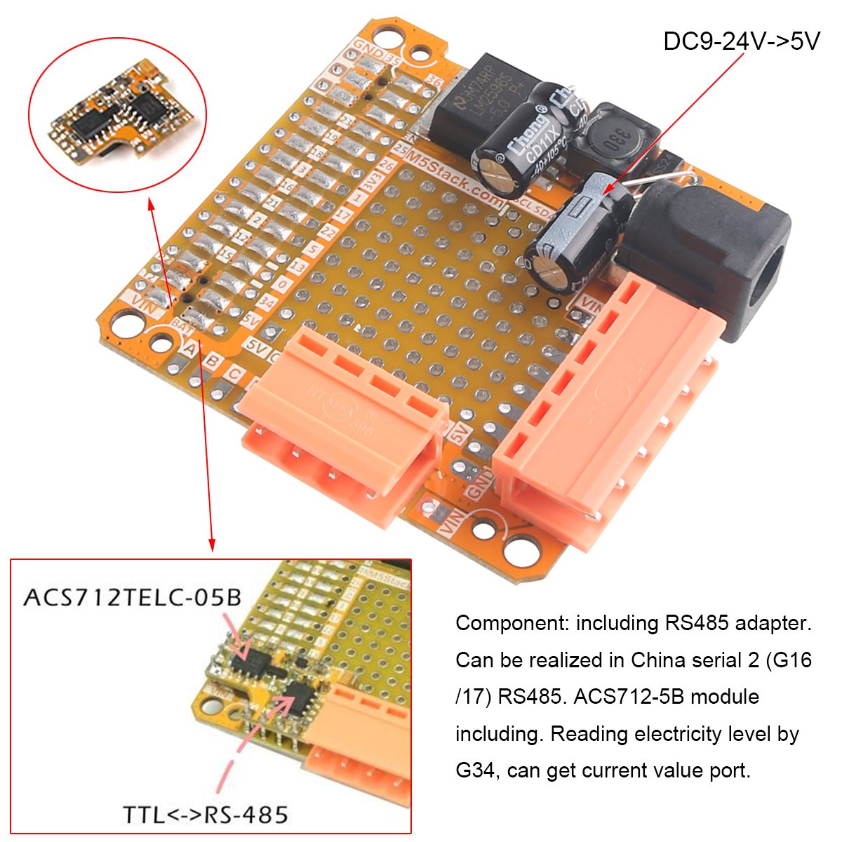
Does the PLC module supply power to the CPU from the 24V input?
Is there an RTS Control line for the RS485 converter or is RTS Control automatic?
(RTS Control is a method with which the RS232 device (typically a PC) tells an RS232-RS485 converter when it should enable its RS485 driver, i.e. when it should be transmitting. http://www.kksystems.com/rtscontrol )
Is there a chip specification for the 485 converter? Which is used?
-
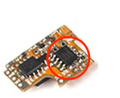
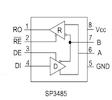
Looks like the 485 driver is a Exar SP3485.
Some vendor on Alibaba claims it is max3485esa replacement.https://datasheet4u.com/datasheet-pdf-file/1103288/Exar/SP3485/1
The SP3485 chip has
Pin 1 - RO - Receiver output
Pin 2 - RE - Receiver Output Enable Active LOW
Pin 3 - DE - Driver Output Enable Active HIGH
Pin 4 - DI - Driver Input
Pin 5 - GND - Ground Connection
Pin 6 - A - Non-Inverting Driver Output/Receiver Input
Pin 7 - B - Inverting Driver Output/Receiver Input
Pin 8 - Vcc - Positive SupplyWhat pin is DE - Driver enable?
Pin 1 - RO -> G16
Pin 2 - RE -> ???
Pin 3 - DE -> ???
Pin 4 - DI -> G17
Pin 5 - GND -> (output port G)
Pin 6 - A -> (output port A)
Pin 7 - B -> (output port B)
Pin 8 - Vcc - 5V (?)Is there a schematic for the little module?
-
I note that the vendor on Amazon is responsive, but not very technical or knowledgeble about the PLC module.
Gave me the schematic for the M5 Core, not the PLC module.
They suggested the ILI9341 (display) RST pin is what I was looking for. No. That's not quite right.
-
I'm waiting for a response supplier via vendor, who assures me that the supplier says it should work as it is and that I don't need RTS. I pointed out that the ESP-IDF documentation for UART indicates that RS485 Half Duplex requires a RTS pin (https://docs.espressif.com/projects/esp-idf/en/latest/api-reference/peripherals/uart.html):
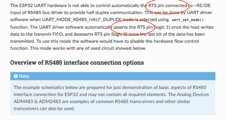
I think I'm going to have to tie a wire between the DE pin on the 3485 to a free GPIO to get the functionality I need.
Hopefully the supplier will eventually provide some official documentation or schematics. I suspect that this might be what you get.
Is anyone from M5Stack here?
-
@mkellner Automatic control of RS485 transceiver data
-
-
This post is deleted! -
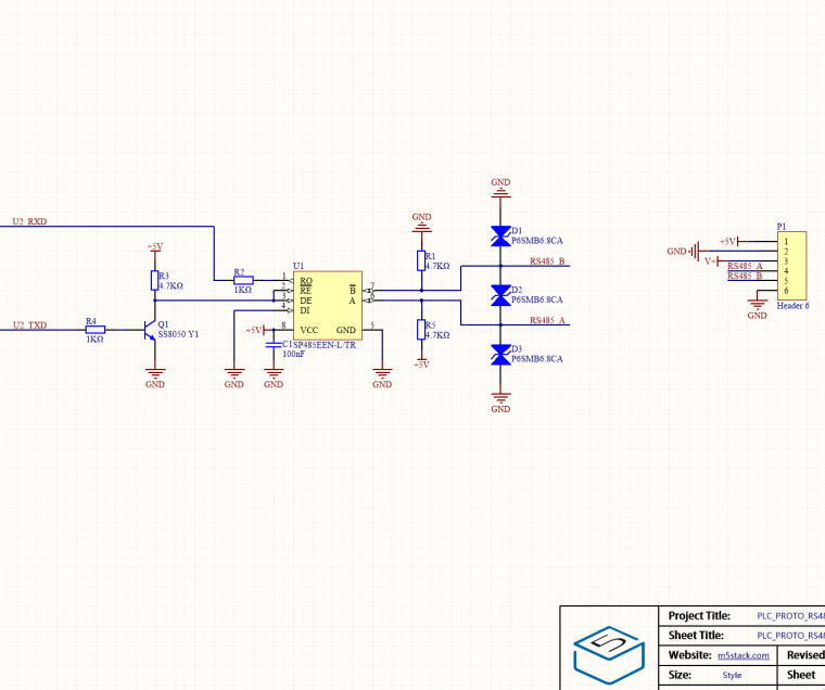
@mkellner Please refer to this schematic diagram.
-
-
@mkellner
Yes the two power pins can supply the complete module, I am using 12V for the ones I have which will also power a LoRa module.
As already answered yes it is automatic, just transmit the data and it is sent out, I am using a Modbus protocol based on one of the Arduino Libraries but it needed a lot of changing to make it compatible with the M5Stack. Works with some Smart Meters I am working with running on the second core of the ESP32 with WiFi and Screen handling on the main Arduino core.You need to make sure you connect all ten connections between the sub board and the main board, there were no instructions with my units so I had to figure them all out. A, B, C and D next to the connector, 5V and GND to the top left of the connector, Vin T2 and R2 on the left side of the main M5Stack connector and if you want to use the current measurement you need to connect pin34 on the right hand side of the main connector. I found the easiest way was to use 0.1" pitch pins and solder them to the small board first and then the main board.
The current measurement is done by the other chip on the small board, it appears to be the current flow into the whole system if the unit is powered from the external power connections marked 24V and G
-
@malbro Would you please explain what needs to be changed in Modbus protocol Library to make it compatible with M5Stack?
-
@kittikoon
true:with ESP-IDF
https://github.com/espressif/esp-idf/tree/master/examples/peripherals/uart/uart_echo_rs485
the RS-485 Demos not fit to ALL your Boards with RS-485.Thanks,
Franz -
-
@franzhoepfinger https://github.com/Fliegl-Agrartechnik-GmbH/M5_COMMS
here some PCBs for test.will post results there.
Hello! It looks like you're interested in this conversation, but you don't have an account yet.
Getting fed up of having to scroll through the same posts each visit? When you register for an account, you'll always come back to exactly where you were before, and choose to be notified of new replies (either via email, or push notification). You'll also be able to save bookmarks and upvote posts to show your appreciation to other community members.
With your input, this post could be even better 💗
Register Login