Where can I find examples of using UART module in UIFlow?
-
in uiflow2 you need to "enable/add" UART in left hand side options below unit picture hardware/software/unit/module then UART is available in blockly
-
Thanks Robski! What i'm confused at is: how can i use those modules? E.g. at the init stage what the different of the first and second block?
 and more details of other UART blocks. Many thanks.
 -
I did nothing, only init a UART module. When i select UART 0, it throws out an error "ValueError: UART buffer size is fixed". When I select UART 1 or 2, it throws out an error "invalid pin"....
There were too insufficient documents! -
understand, i can see same, UART implementation looks different in Uiflow 1 blockly and it works.
uiflow1
uart1 = machine.UART(1, tx=17, rx=16)
uart1.init(9600, bits=8, parity=None, stop=1)uiflow2
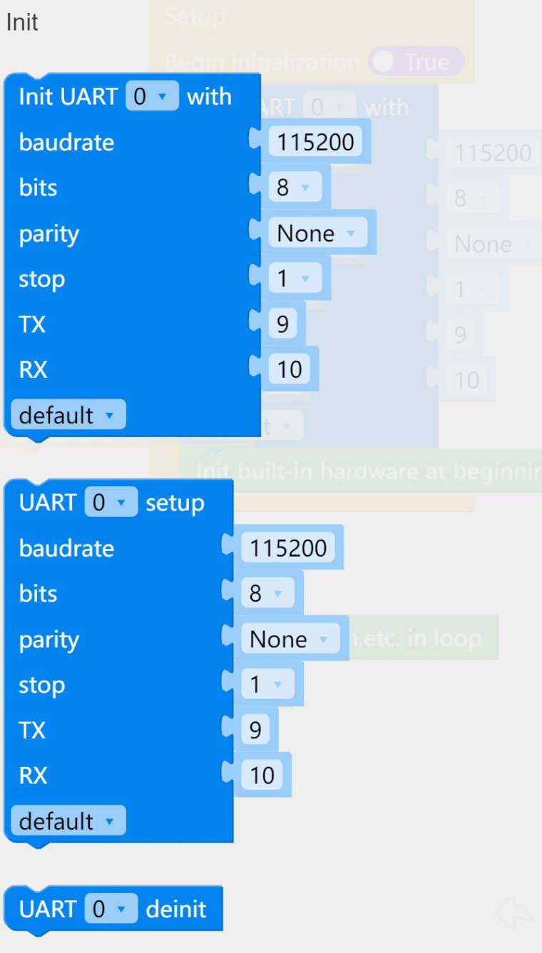
setup block:
uart0.init(baudrate=115200, bits=8, parity=None, stop=1, tx=17, rx=16, rts=-1, cts=-1, txbuf=256, rxbuf=256, timeout=0, timeout_char=0, invert=0, flow=0)init block:
uart0 = UART(0, baudrate=115200, bits=8, parity=None, stop=1, tx=17, rx=16, rts=-1, cts=-1, txbuf=256, rxbuf=256, timeout=0, timeout_char=0, invert=0, flow=0) -
Hello @zhoubinx
in UIFlow2 the UART blocks, unfortunately, are broken (for M5CoreS3 at least). Using UART1 tries to initialize
rtsandctswith-1which leads to the "invalid pin" error.@m5stack : please fix. Thank you.
But there is a way to get around that error using the
Execute mpy codeblock and omitting the extended parameters likertsetc.. I've uploaded an example into the UIFlow2 Play Zone called: M5CoreS3_UART_PortC_UIFlow2.0.1Thanks
Felix -
@zhoubinx said in Where can I find examples of using UART module in UIFlow?:
I didn't find any examples in Github either
@zhoubinx for some examples go to uiflow1 flow.m5stack.com then under UART blocks you can find pass thru and sim800 examples
-
@felmue Thanks alot! I will study your example!
-
@robski Thanks alot robski! Thanks for your clue about uiflow 1, so I tried to code in mpy, “from machine import UART”. At least, it no longer crashes, but still can't read and write data, I will keep on trying and let everyone know.
-
@felmue I studied your example. Can I know what device you used to connect to S3 through the UART port(port C of the S3 core)? On my side it still doesn't work, can't read anything neither write out. I noticed in the introduction of S3, there is an official note:"Q: After the sensor is connected, what is the case that the sensor does not work or does not exist?
A: The CoreS3 uses the AXP2101 power management chip, and the Port port and the M5-Bus power supply need to be configured for normal output voltage. The configured API is in the AXP2101.cpp library file, and can be configured as required. eg: M5.Axp.powerModeSet(POWER_MODE_USB_OUT_BUS_OUT) in the setup function."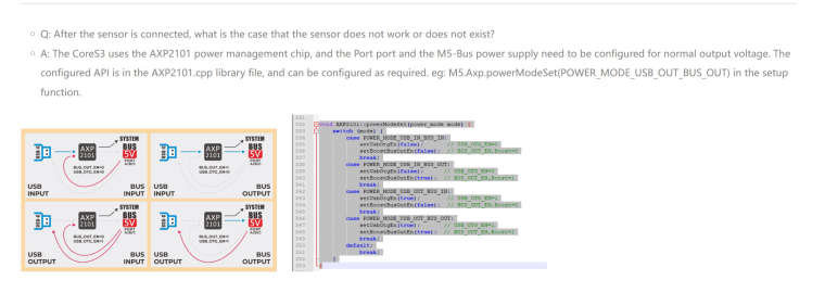
Would that be the reason? How can I do that in mpy? In your mpy and C project, you never use this powerModeSet function.
Many thanks again!
-
Hello @zhoubinx
there is no need for that when using UIFlow2. UIFlow2 firmware automatically turns the power on for all ports. (The FAQ comment is only relevant when programming with Arduino.)
What is the serial device you are trying to read from and write to? (I was testing with a SIM7080 modem, btw.)
Thanks
Felix -
@felmue Understand! Thanks! I'm using a 3rd part device, not M5's product.
-
Hello @zhoubinx
please note: while Groove ports on M5Stack cores provide 5 V power, the data pins are only 3.3 V tolerant. Which means you might need some level shifters to make a third party product work.
Do you have a link to that 3rd party product?
Thanks
FelixGPIO translation table M5Stack / M5Core2
Information about various M5Stack products.
Code examples -
@felmue As a side note:
I had a project where the third party sensor was 5V intolerant.
I chose the Stamp-PICO with the USB Downloader accessory (and the Stamp-ISP) are 3.3V (!) -
@felmue Thanks Felix! The device i'm working on is an Arduino 328P board, there were a UART port on the board (as far as the info i have, there printed "UART port", not I2C or whatever). It's a quite old device, it's difficult find link and more introduction. And it is the control board of an open source laser engraver machine.
I will try your suggestion of the port voltage. And I also ordered a M5 UART GPS module, I will try that module to get more understanding of serials port programing first. -
@felmue I tested my target device the PIN is 3.3V, so, I need to downgrade M5 from 5V to 3.3V? Many thanks!
-
@zhoubinx M5 gpio/ grove are 3.3v so if your device side is 3.3 then all good, be sure that tx goes to rx and rx to tx, same baudrate and parity ....
-
Hello @zhoubinx
like @robski already mentioned, you only need level shifter if your target board TX and RX pins are different from M5Stack Groove port, which uses 3.3 V on its data pins. (Only the red wire of the Groove port, providing power to the M5Stack units, is 5 V.)
Are you sure your target board uses 3.3 V on the data pins? Arduino boards (especially old ones) mostly use 5 V on their data pins.
Thanks
Felix -
 It looks like the bad thing is from AXP2101 power chip, all the PORTs were set to 5V? Please, any idea of how to lower voltage to 3.3V.
I will also find a multimeter to give a test. -
Hello @zhoubinx
I am not sure you fully understand the concept of how the Groove port of M5Stack devices are setup.
- Power (red wire) provides 5 V to M5Stack units (which if required turn the 5 V internally to 3.3 V using an DC/DC converter or LDO).
- Data lines (yellow and white wire) use 3.3 V
- GND (black wire)
In your case I assume the 3rd party device (Arduino) is already powered by its own power supply. If yes, then there is no need to use the power (red wire) of the M5Stack.
If the 3rd party device is using 3.3 V on its data lines (TX and RX) then the wiring is as follows:
M5Stack (3.3 V) TX <---> RX (3.3 V) of 3rd party device
M5Stack (3.3 V) RX <---> TX (3.3 V) of 3rd party device
M5Stack GND <---> GND of 3rd party deviceIf the 3rd party device is using 5 V on its data lines (Tx and RX) then the wiring is as follows:
M5Stack (3.3 V) TX <---> Level shifter <---> RX (5 V) of 3rd party device
M5Stack (3.3 V) RX <---> Level shifter <---> TX (5 V) of 3rd party device
M5Stack GND <---> GND of 3rd party deviceHere is an example M5Stack unit which uses an DC/DC converter to lower the 5 V to 3.3 V and includes level shifters for the data lines. See schematic.
Thanks
Felix -
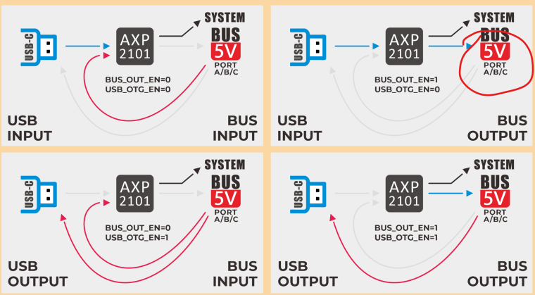
@zhoubinx said in Where can I find examples of using UART module in UIFlow?:
It looks like the bad thing is from AXP2101 power chip, all the PORTs were set to 5V? Please, any idea of how to lower voltage to 3.3V.
I will also find a multimeter to give a test.on your graphic USB-C is not PORT C (blue) - unfortunately it is drawn in blue - but this is USB port which you are connecting your Laptop /pc to M5Stack
in general on Ports A/B/C wires blk/red are power pins with gnd/5v on them where other two pins wht/yellow are data/sensor pins with 3.3v expected
Hello! It looks like you're interested in this conversation, but you don't have an account yet.
Getting fed up of having to scroll through the same posts each visit? When you register for an account, you'll always come back to exactly where you were before, and choose to be notified of new replies (either via email, or push notification). You'll also be able to save bookmarks and upvote posts to show your appreciation to other community members.
With your input, this post could be even better 💗
Register Login