🤖Have you ever tried Chat.M5Stack.com before asking??😎
    M5Stack Community
    • Categories
    • Recent
    • Tags
    • Popular
    • Users
    • Groups
    • Search
    • Register
    • Login

    ATOM-DTU-NB-IoT - modem does not respond anymore

    Atom
    6
    27
    12.2k
    Loading More Posts
    • Oldest to Newest
    • Newest to Oldest
    • Most Votes
    Reply
    • Reply as topic
    Log in to reply
    This topic has been deleted. Only users with topic management privileges can see it.
    • E
      erazor
      last edited by erazor

      Hi, I was playing with the DTU-NB some days ago until suddenly the modem stopped responding to any AT command.

      So I bought two new devices, and now none respond anymore.

      For testing I started to use "TinyGsmAutoBaud" (I also modified the code to use the correct PINs). With my first broken DTU - no response to any Baudrate.

      Since I seemed to broke the second module already and the TinyGsmAutoBaud also does not respond I simply put the Atom into my third unused DTU - which worked and got a response with 115200 - so the TinyGsmAutoBaud and Firmware seems to work.

      I tried the same Atom on my second (broken) DTU with no success. So I resumed playing with the third DTU, and pressed the rest button - and finally this one also does not respond.

      Is this a hardware issue? Any way to get the broken devices running again?

      Thanks for your time.

      1 Reply Last reply Reply Quote 0
      • felmueF
        felmue
        last edited by

        Hello @erazor

        in my experiments with different modems (SIM7020, SIM7080, SIM7600 etc.) I found that some want a specific line ending to work reliably. I have the best result with \r only. \r\n\ kind of works and \n doesn't work for me.

        So, you could try to modify the TinyGsmAutoBaud code to only send an "AT\r" instead of the default "AT\r\n". See this line.

        Thanks
        Felix

        GPIO translation table M5Stack / M5Core2
        Information about various M5Stack products.
        Code examples

        1 Reply Last reply Reply Quote 0
        • E
          erazor
          last edited by

          Well, yes.... "AT\r" should be enough and this was even mentioned in the datasheets.

          Anyway, mostly people use tinyGSM and "AT\r\n" should work anyway.

          I tried "AT\r" - no difference, the modem remains silent. I also tried a USB-USART connection with 3.3V levels and tried different baudrates, spamming the modem with any combination of "AT\r\n" - no success.

          Normally it has autobaud, if not it should start with "RDY" - I'm not getting anything with powerup. The modems LEDs blink but thats all.

          I saw that they're translating the logic-levels from 3.3V to 1.8V. I'm not sure but these are looking completely strange to me.

          0_1676556849878_IMAG001.BMP

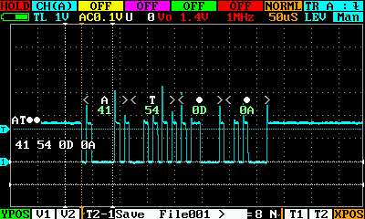
          There shouldn't be any 3.3V peaks, right? The image shows my TX line, somewhere at transistor Q3. NB_RX and U1_RX are looking quite similar, so maybe the transistor is broken?

          1 Reply Last reply Reply Quote 0
          • felmueF
            felmue
            last edited by

            Hello @erazor

            I agree, I wouldn't expect 3.3 V peaks at the U1_RX side of the Q3. And yes, I guess the transistor could be broken, but it being broken in three devices - that is a bit hard to imagine.

            I never have used the TinyGsmAutoBaud code myself. I normally run all my modems with just 115200 and so far that worked just fine.

            Have you tried to measure what comes out of the modem, e.g. at transistor Q5? Maybe you can determine from that what baudrate the modem expects?

            Thanks
            Felix

            GPIO translation table M5Stack / M5Core2
            Information about various M5Stack products.
            Code examples

            E 1 Reply Last reply Reply Quote 0
            • E
              erazor @felmue
              last edited by

              @felmue there is nothing. I also removed and replaced Q3 with Q5. My idea was, that maybe Atom-RX line became output and killed Q3 but that's not the case.

              Removing the Q5 completely changed nothing.

              I ordered another two modules to check the signals but I start to think the issue is in the modem.

              Maybe I come to a point where I should ask the M5 team for help. This is kinda annoying, I really like the design of the DTU.

              1 Reply Last reply Reply Quote 0
              • felmueF
                felmue
                last edited by

                Hello @erazor

                ok, I see. Yes, I think getting in touch with M5Stack support is probably best.

                Thanks
                Felix

                GPIO translation table M5Stack / M5Core2
                Information about various M5Stack products.
                Code examples

                E 1 Reply Last reply Reply Quote 0
                • E
                  erazor @felmue
                  last edited by

                  @felmue thanks for your hints and your time!

                  1 Reply Last reply Reply Quote 0
                  • F
                    Forairaaaaa Global Moderator
                    last edited by

                    Hi, can you offer me that code when the modem stopped responding? To see if my DTU will meets the same issue

                    E 2 Replies Last reply Reply Quote 0
                    • E
                      erazor @Forairaaaaa
                      last edited by

                      Update for anybody who's reading this.

                      My previous assumption that the reset-button kills the modem seems incorrect.

                      I've had another two devices and carefully did not use the reset-button at all but these modules also stopped working.

                      1 Reply Last reply Reply Quote 0
                      • E
                        erazor @Forairaaaaa
                        last edited by

                        @forairaaaaa you can find my code here:
                        https://github.com/erazor83/nb_dtu_reset_issue/

                        1 Reply Last reply Reply Quote 0
                        • F
                          Felix22
                          last edited by

                          i can not use this code, Error:

                          In file included from N:.....\nb_dtu_reset_issue-main\src\main\main.ino:21:
                          c:\Users\fb\Documents\Arduino\libraries\TinyGSM\src/TinyGsmClient.h:118:2: error: #error "Please define GSM modem model"
                          #error "Please define GSM modem model"
                          ^~~~~
                          exit status 1

                          Compilation error: exit status 1

                          1 Reply Last reply Reply Quote 0
                          • felmueF
                            felmue
                            last edited by

                            Hello @Felix22

                            please do not use the nb_dtu_reset_issue code - it was meant to debug an issue and can change the baudrate of the SIM7020 modem.

                            Thanks
                            Felix

                            GPIO translation table M5Stack / M5Core2
                            Information about various M5Stack products.
                            Code examples

                            J 1 Reply Last reply Reply Quote 0
                            • J
                              johseffer @felmue
                              last edited by

                              @felmue you solve that? Happened with me today, i think after i send a "AT&F" to factory reset the configurations, so now my module stop reply to at commands

                              felmueF 1 Reply Last reply Reply Quote 0
                              • felmueF
                                felmue @johseffer
                                last edited by

                                Hello @johseffer

                                yes. See here.

                                Thanks
                                Felix

                                GPIO translation table M5Stack / M5Core2
                                Information about various M5Stack products.
                                Code examples

                                F 1 Reply Last reply Reply Quote 0
                                • F
                                  fkarner @felmue
                                  last edited by

                                  Hello,

                                  I'm working as well with the above mentioned hardware (7020G modem). For a while the program worked fine. Unfortunately since some time the modem does not respond anymore.

                                  The example MQTT code given here does not work (no errors). I think I'm using the needed libraries, so I would not expect errors coming from there. The here already mentioned way to solve the problem by changing the baudrate was not successfull - still silence.

                                  The Serial Monitor Output indicates that the initialisation is not possible:
                                  21:23:10.998 -> waiting....1067s
                                  21:23:26.485 -> waiting....1082s
                                  21:23:41.922 -> waiting....1098s
                                  21:23:57.420 -> waiting....1113s
                                  21:24:12.866 -> waiting....1129s
                                  21:24:28.348 -> waiting....1144s
                                  21:24:43.793 -> waiting....1159s
                                  21:24:59.276 -> waiting....1175s

                                  so the M5Atom is still stuck here:

                                   while (!modem.init()) {
                                          log("waiting...." + String((millis() - start) / 1000) + "s");
                                      };
                                  

                                  I really don't know how to solve this problem. Since I'm not an expert in programming I would be thankful if someone could help me out with a code to send simple AT-Commands via the Serial Input.

                                  Thanks in advance
                                  flori

                                  felmueF 1 Reply Last reply Reply Quote 0
                                  • felmueF
                                    felmue @fkarner
                                    last edited by

                                    Hello @fkarner

                                    hmm, since you already tried changing the modem baudrate I am at a loss what might have gone wrong.

                                    Maybe my serial pass-through example can shed some light onto this issue?

                                    Thanks
                                    Felix

                                    GPIO translation table M5Stack / M5Core2
                                    Information about various M5Stack products.
                                    Code examples

                                    F 1 Reply Last reply Reply Quote 0
                                    • F
                                      fkarner @felmue
                                      last edited by fkarner

                                      @felmue said in ATOM-DTU-NB-IoT - modem does not respond anymore:

                                      hmm, since you already tried changing the modem baudrate I am at a loss what might have gone wrong.

                                      Hi Felix,

                                      thank you very much for your answer and the code example. I can upload the code, without errors. The Atom stops here:

                                      19:19:49.162 -> ets Jun 8 2016 00:22:57
                                      19:19:49.162 ->
                                      19:19:49.162 -> rst:0x1 (POWERON_RESET),boot:0x13 (SPI_FAST_FLASH_BOOT)
                                      19:19:49.162 -> configsip: 188777542, SPIWP:0xee
                                      19:19:49.162 -> clk_drv:0x00,q_drv:0x00,d_drv:0x00,cs0_drv:0x00,hd_drv:0x00,wp_drv:0x00
                                      19:19:49.162 -> mode:DIO, clock div:1
                                      19:19:49.162 -> load:0x3fff0030,len:1344
                                      19:19:49.162 -> load:0x40078000,len:13964
                                      19:19:49.162 -> load:0x40080400,len:3600
                                      19:19:49.162 -> entry 0x400805f0
                                      19:19:51.594 -> Start SIM7020 passthrough test

                                      Unfortunately I do not get answer thru the serial monitor... I've tried:
                                      AT+CEER=?, AT+CGMI=?, AT+CFUN=1. No response... By the way the modem LED's show acitivity red is on, blue flashes with ~.5Hz....

                                      After that I reinstalled Arduino IDE. Now there are only the M5Stack Boards and the Arduino Boards listed. As Libraries I installed only the M5Unified and the M5GFX. I'm clueless. What could I try next?

                                      Update: I've tried another 7020G modem. That one answers....

                                      *19:43:58.890 -> ets Jun 8 2016 00:22:57
                                      19:43:58.890 ->
                                      19:43:58.890 -> rst:0x1 (POWERON_RESET),boot:0x13 (SPI_FAST_FLASH_BOOT)
                                      19:43:58.922 -> configsip: 188777542, SPIWP:0xee
                                      19:43:58.922 -> clk_drv:0x00,q_drv:0x00,d_drv:0x00,cs0_drv:0x00,hd_drv:0x00,wp_drv:0x00
                                      19:43:58.922 -> mode:DIO, clock div:1
                                      19:43:58.922 -> load:0x3fff0030,len:1344
                                      19:43:58.922 -> load:0x40078000,len:13964
                                      19:43:58.922 -> load:0x40080400,len:3600
                                      19:43:58.922 -> entry 0x400805f0
                                      19:44:01.378 -> Start SIM7020 passthrough test
                                      19:44:04.165 -> AT+CEER=?

                                      19:44:04.197 -> +CEER: (0,1)
                                      19:44:04.197 ->
                                      19:44:04.197 -> OK
                                      19:44:14.518 -> AT+CGMI=?*

                                      Thanks, flori

                                      felmueF 1 Reply Last reply Reply Quote 0
                                      • felmueF
                                        felmue @fkarner
                                        last edited by

                                        Hello @fkarner

                                        thank you for the update. So it's confirmed something's wrong with the first SIM7020G. I still suspect the baudrate got changed somehow, especially since you are writing that the LEDs behave normally.

                                        Thanks
                                        Felix

                                        GPIO translation table M5Stack / M5Core2
                                        Information about various M5Stack products.
                                        Code examples

                                        F 1 Reply Last reply Reply Quote 0
                                        • F
                                          fkarner @felmue
                                          last edited by

                                          Hi @felmue

                                          Yes I agree, there must be something wrong with this module. I will investigate that later... First priority is to set up one DTU NB IOT module.

                                          Unfortunately also with the working modem I get errors using the MQTT code example:

                                          12:37:55.848 -> Initializing modem...
                                          12:37:55.848 -> [ 62][E][esp32-hal-gpio.c:102] __pinMode(): Invalid pin selected
                                          12:37:55.848 -> E (61) gpio: gpio_set_level(227): GPIO output gpio_num error
                                          12:37:56.138 -> E (364) gpio: gpio_set_level(227): GPIO output gpio_num error

                                          May they come from the reistallation of Arduino IDE?
                                          Here are my compiling settings:
                                          confi.png

                                          I found the error code here. For sure there must be something wrong with the serial communication.... Strange....

                                          flori

                                          felmueF 1 Reply Last reply Reply Quote 0
                                          • felmueF
                                            felmue @fkarner
                                            last edited by

                                            Hello @fkarner

                                            I get the same error, but it's not fatal. The error stems from the fact that in ATOM_DTU_NB.h a GPIO is defined, e.g.

                                            #define ATOM_DTU_SIM7020_RESET -1
                                            

                                            for the SIM7020 reset which isn't connected in the DTU.
                                            If you change that to something like 13 the error goes away.

                                            The program is probably stuck in Inititalzing modem as it tries to check for the SIM card and that it doesn't have a PIN defined.

                                            Have you double-checked that the SIM card is placed in the correct orientation and that it doesn't use a PIN?

                                            Thanks
                                            Felix

                                            GPIO translation table M5Stack / M5Core2
                                            Information about various M5Stack products.
                                            Code examples

                                            F 1 Reply Last reply Reply Quote 0
                                            • First post
                                              Last post