Update: some further notes and a workaround solution.
I decided to dig a bit deeper into how the BM8563 RTC works and how it is initialized by the M5Stack Arduino C++ library. Without going into all the details I have so far found out the following:
Taking out the battery and leaving the CoreINK powerless does not in it self lead to the problem, as I have stated earlier in this thread. I seems the reason is some registers of the RTC sometimes become corrupted. Exactly how this happens, I'm not sure of, but one way may be when power (aka. the battery) is removed while data are written via I2C to the RTC. Important is however the matter of the fact: it can happen!
Apparently the the UIFlow firmware does not reset these registers correctly at start up. Digging into the Arduino library (which I knew could fix problem) I found the RTC init routine which resets the three control registers* of the BM8563. I then thought I could do the same with the I2C library in UIFlow. And sure enough, it works. So the workaround is to run the following code:
import i2c_bus

i2c0 = i2c_bus.easyI2C(i2c_bus.M_BUS, 0x51, freq=400000)
i2c0.write_u8(0x00, 0x00)
i2c0.write_u8(0x01, 0x00)
i2c0.write_u8(0x0D, 0x00)
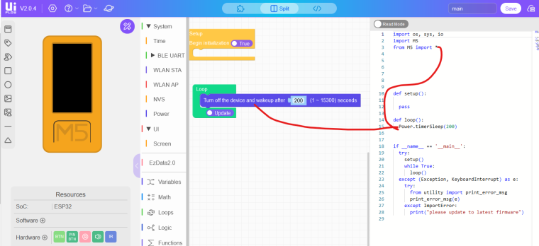
some where in your script before the
m5stack.power.restart_after_seconds(n)
is called.
I haven't tested but I suppose it is the same if you use:
m5stack.power.restart_on(minutes=n, hours=n, date=n, weekday=n)
Notes to above code:
Please use the UIFlow I2C library (import i2c_bus) as the native Micropython I2C library (machine.I2C) messes up the "internal" I2C communication of the UIFlow firmware.
i2c_bus.M_BUS = (21,22) aka I2C pins for the BM8563 on the CoreINK
0x51 is the I2C address of the BM8563
0x00,0x01 and 0x0D are the control registers which are set to 0x00
The Arduino library for RTC init for comparison :
void RTC::begin(void) {
    Wire1.begin(21, 22);
    WriteReg(0x00, 0x00);
    WriteReg(0x01, 0x00);
    WriteReg(0x0D, 0x00);
}
*) please refer to the BM8563 datasheet for further details.