Lesson 20. GROVE GPIO + Potentiometr. KingPong Game
-
The purpose of this lesson
Hi! Today we will learn how to use a variable resistor to control a tennis racket in a Ping Pong game.
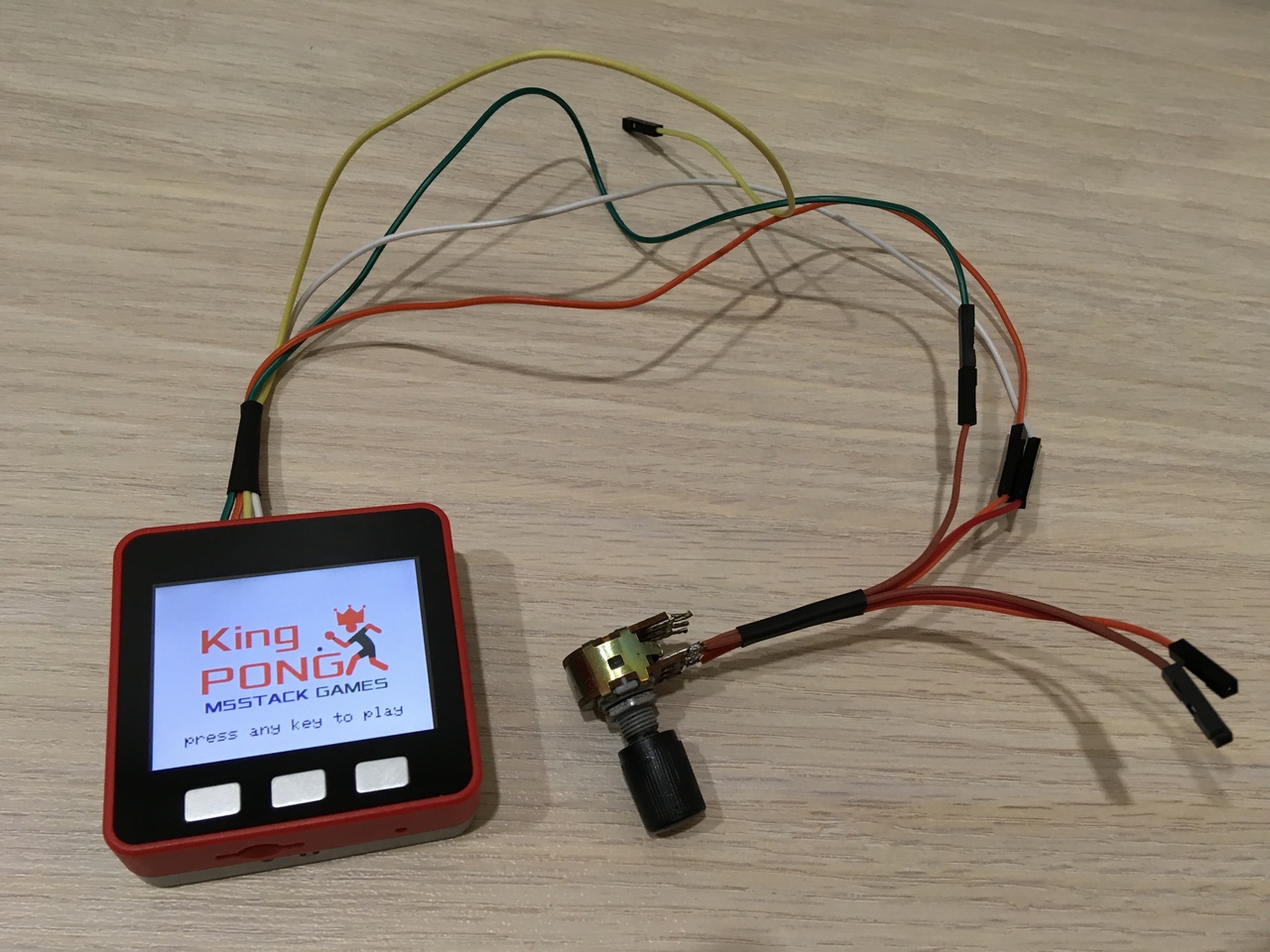
Figure 1
This tutorial will teach you how to use the GROVE GPIO port to connect an input device and use this as an example of a game.
Short help
Table tennis (sometimes colloquially mistakenly used the name ping-pong) — Olympic sport, athletic game ball, which uses a racket and a table separated by a net. The game can take place between two opponents or two pairs of opponents. The task of the players is to use the rackets to send the ball to the opponent so that he could not return it back in accordance with the rules. p.s. In our case, the player will play with himself.
More on Wiki: https://en.wikipedia.org/wiki/Table_tennis
List of components for the lesson
- PC/MAC;
- M5STACK FIRE;
- USB-C cable from standard set;
- variable resistor;
- colored wires from the standard set (type plug-socket);
- colored wires not from the standard set (socket type);
- wire cutters;
- shrinkage;
- needle;
- soldering iron and solder.
Let's start!
Step 1. Do adapter (if there is no factory)
The m5fire has GROVE GPIO connector, but unfortunately the standard wires will not work. You need an adapter with a plug, if you do not have it, now we will figure out how to fix it.
The first step is to use a needle to bend the latch on the outlet and remove the contact (Fig. 2).
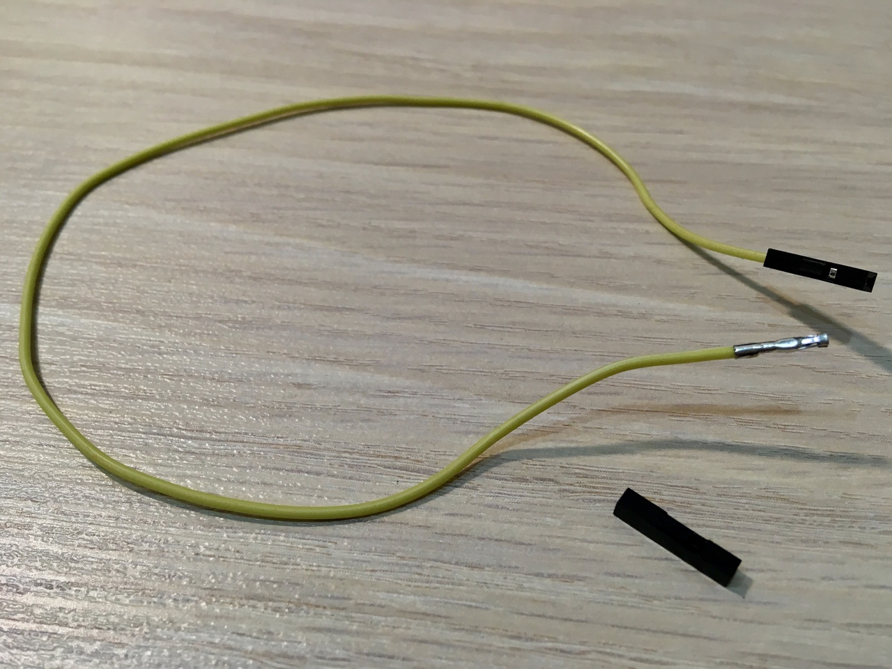
Figure 2
Good. Now take the wire cutters and gently squeeze evenly around the contact. During this process, make a fitting by connecting to any of the four contacts from the black connector (PORT B M5FIRE) (Fig. 3). We need to compress the four pins on the four wires.
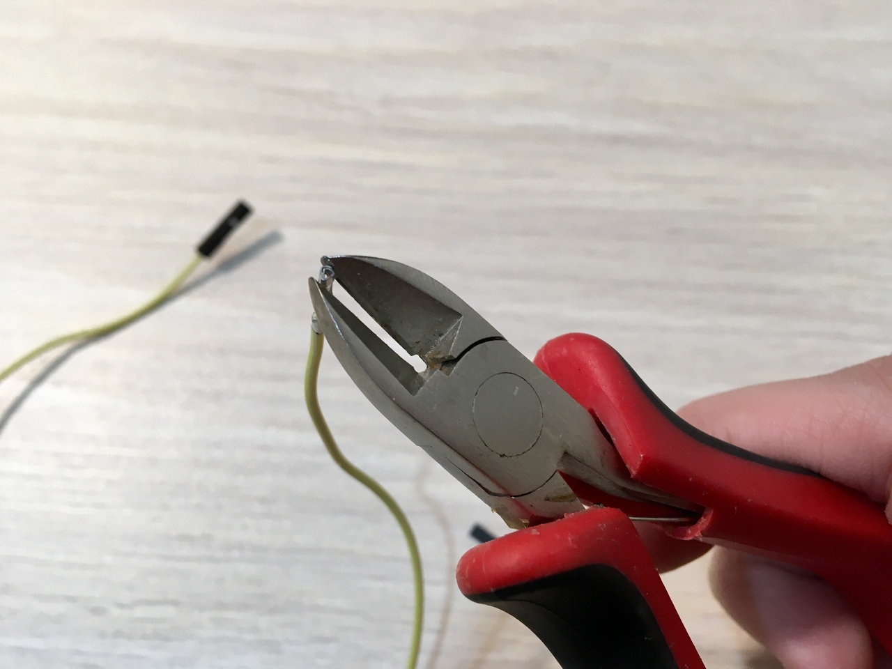
Figure 3
When all four wires are crimped, it is necessary to return the plastic insulators to two of them. Then connect all the wires and press the heat shrink (Fig. 4).
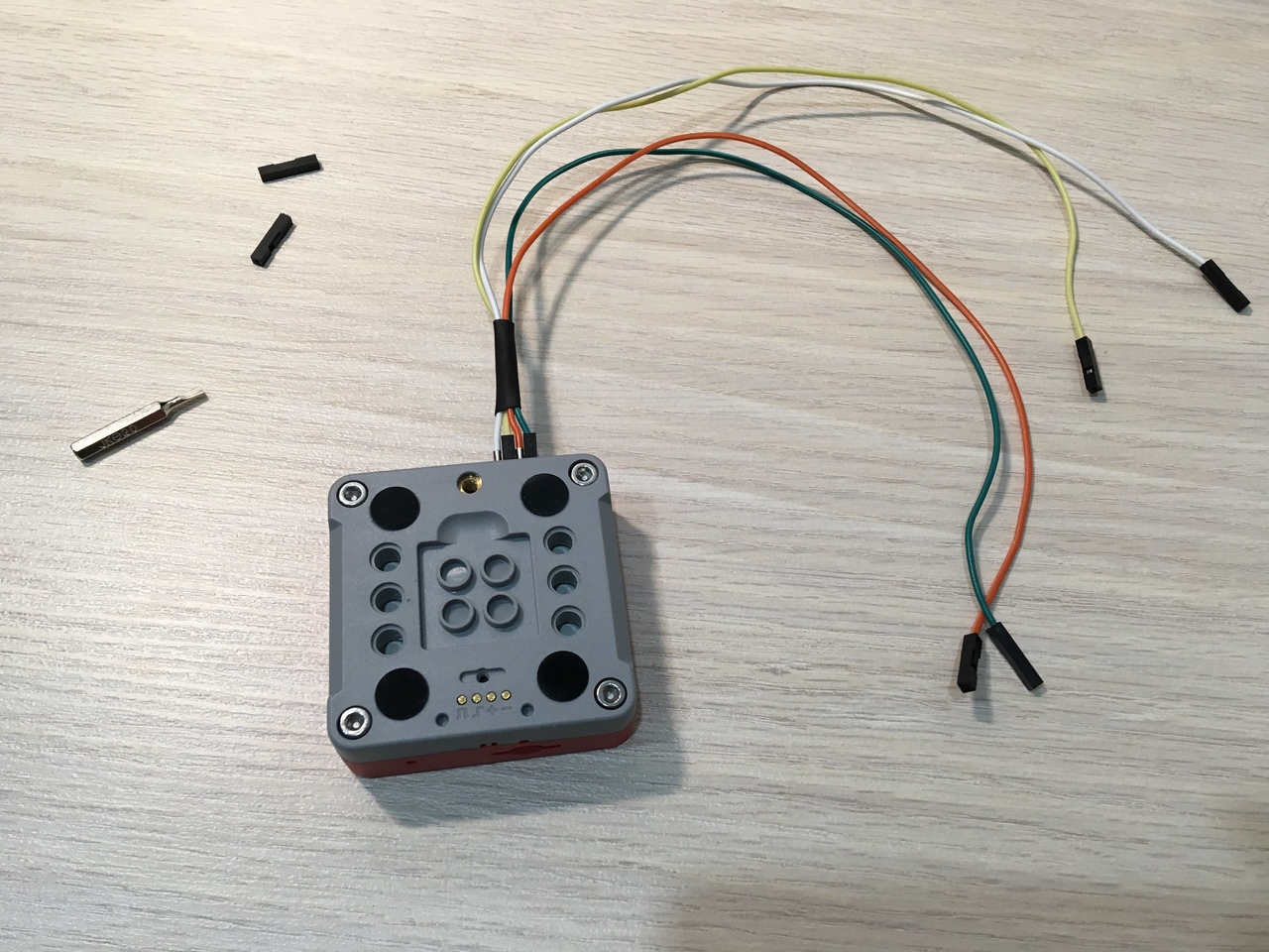
Figure 4
Once the wires are connected to the device, it is not recommended to remove them unnecessarily (Fig. 5 - 6).
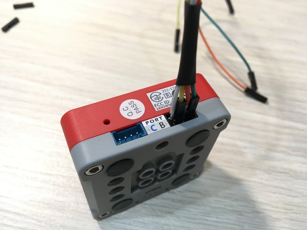
Figure 5
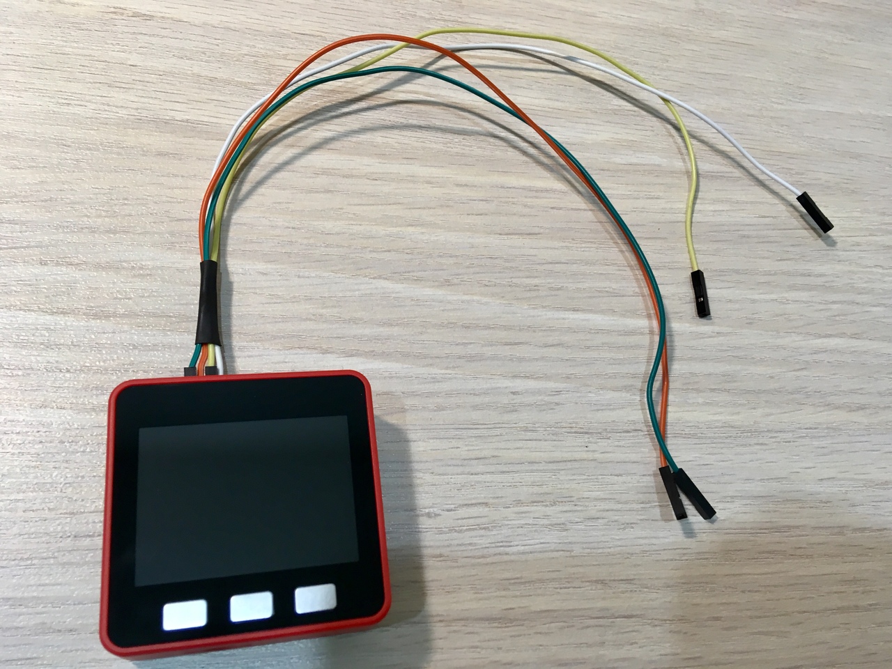
Figure 6
Step 2. Preparation and connection of the variable resistor
Solder two pairs of three wires to the variable resistor (Fig. 7). Right wire connect to +5 V, Central to 36, left to GND (Fig. 1).
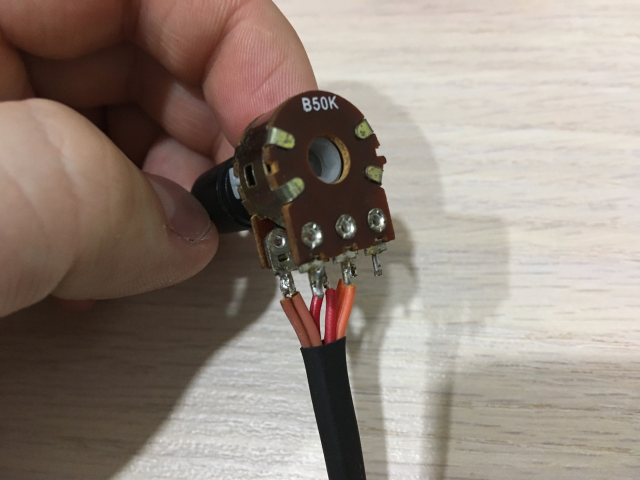
Figure 7
Step 3. Sketch
The code of the game is very simple, let's look at an interesting point in this lesson:
Find out the input voltage. Do not forget that the reference voltage is 3.3 V, and we supply 5 V. more than 3.3 V ADC does not understand:
int voltage = analogRead (36) * 3400 / 4096;Convert to percentages:
int percentage = voltage * 100 / 3400;Calculate the position of the racket:
raket_position = map(percentage, 0, 100, 0, 10);Each time we will draw all ten rackets, but only the active will be red, and the remaining white:
for (int i = 0; i < 10; i++)
{
  if (i < 5)
  {
    x = 0;
    y = i * (raket_height + raket_margin);
  }
  else
  {
    x = screen_width - raket_width;
    y = (9-i) * (raket_height + raket_margin);
  }
  color = (i == raket_position) ? RED : WHITE;
  M5.Lcd.fillRect(x, y, raket_width, raket_height, color);
  ledBar(0, 0, 0, 12);
  ledBar(255, 0, 0, 9 - raket_position);
  if (i == raket_position)
  {
    raket_x = x;
    raket_y = y;
  }
}
Final step
That's all (Fig. 8). Can be played on a record :)
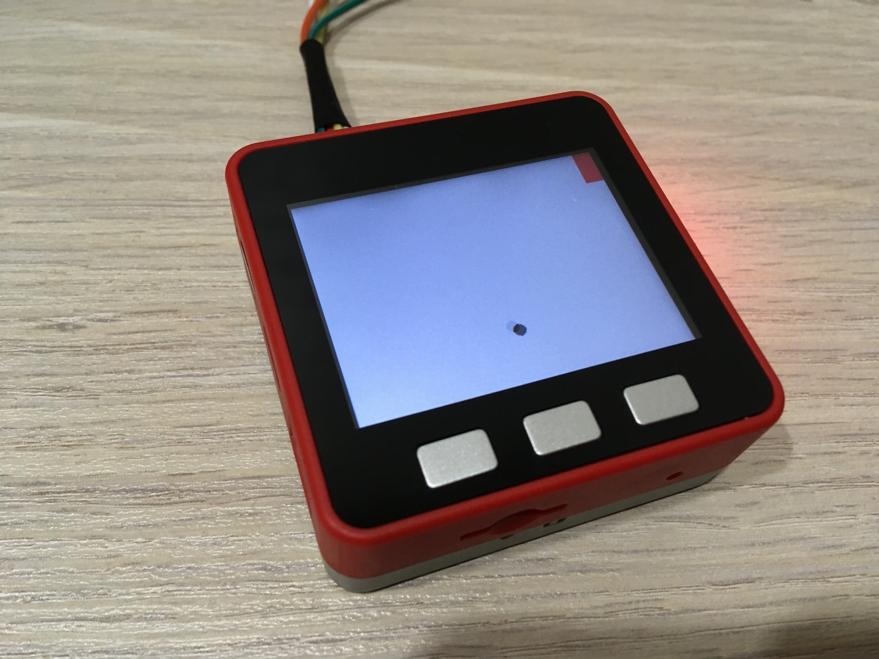
Figure 8
Downloads
- Sketch + LED library (GitHub): https://github.com/dsiberia9s/Lesson-20_KingPong_Game